Capacitive type humidity sensor

Inactive Publication Date: 2005-09-01
DENSO CORP
View PDF12 Cites 45 Cited by
  • Summary
  • Abstract
  • Description
  • Claims
  • Application Information

AI Technical Summary

Benefits of technology

[0008] In view of the above-described problem, it is an object of the present invention to provide a capacitive type humidity sen

Problems solved by technology

Further, the sensor has a small size and a low manufacturing cost.
Further, the humidity devices, the standard capacitance device and the CV converter

Method used


Image

  • Capacitive type humidity sensor
  • Capacitive type humidity sensor
  • Capacitive type humidity sensor

Examples


first embodiment

[0026] A capacitive type humidity sensor according to a first embodiment of the present invention is described as follows. Firstly, an operation of the sensor is described with reference to FIGS. 1A to 1C.

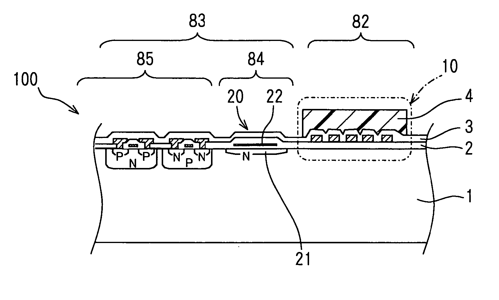
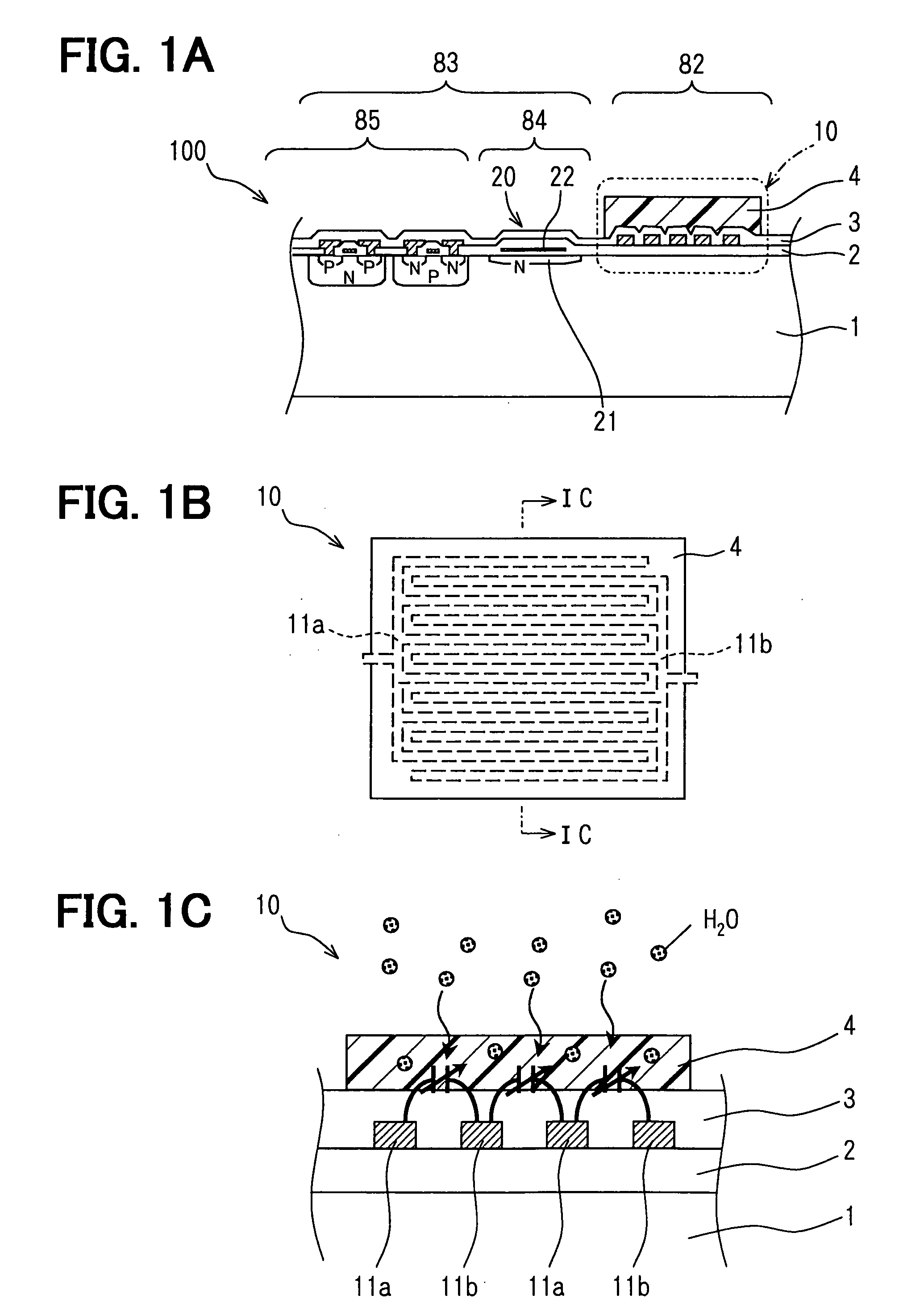
[0027]FIG. 1A shows a main part 100 of the sensor 101 schematically, and FIGS. 1B and 1C show a humidity device 10 of the main part 100.

[0028] The main part 100 of the sensor 101 includes a semiconductor substrate 1 having one surface, on which a moisture sensitive portion 82 and a circuit portion 83 are disposed. The moisture sensitive portion 82 includes the humidity device 10. The substrate 1 is made of silicon. The circuit portion 83 includes a CMOS transistor portion 85 and a standard capacitance portion 84. The standard capacitance portion 84 includes a standard capacitance device 20.

[0029] The humidity device 10 includes a pair of comb-teeth electrodes 11a, 11b, which is disposed separately on the substrate 1 to face each other. Specifically, comb-teeth of one electrode 1...

second embodiment

[0042] A capacitive type humidity sensor 102 according to a second embodiment of the present invention is shown in FIG. 3. The sensor 102 includes two humidity devices 10a, 10b, one standard capacitance device 20b and the CV converter circuit 30. The humidity devices 10a, 10b share the standard capacitance device 20b commonly. Thus, in the sensor 102, the number of the standard capacitance devices 20b is reduced so that the area occupied by the standard capacitance device 20b is reduced. Thus, the dimensions of the sensor 102 are much reduced.

third embodiment

[0043] A capacitive type humidity sensor 103 according to a third embodiment of the present invention is shown in FIGS. 4A and 4B. The sensor includes two humidity devices 10a, 10b, two standard capacitance devices 20a, 20b and the CV converter circuit 30. The humidity devices 10a, 10b are disposed on the standard capacitance devices 20a, 20b through an insulation layer 5. Thus, the plan area occupied by the humidity devices 10a, 10b and the standard capacitance devices 20a, 20b is reduced since the humidity devices 10a, 10b and the standard capacitance devices 20a, 20b are laminated together. Thus, the dimensions of the sensor 103 are much reduced.


PUM


Abstract

A capacitive type humidity sensor includes: a semiconductor substrate; a plurality of humidity devices having a capacitance variable in accordance with a humidity; a standard capacitance device having a standard capacitance, a capacitance change of which in accordance with the humidity is smaller than that of the capacitance of each humidity device; and a CV converter circuit for converting a capacitance difference between the capacitance of each humidity device and the standard capacitance of the standard capacitance device to a signal voltage. The humidity devices, the standard capacitance device and the CV converter circuit are disposed on one side of the substrate.

Description

CROSS REFERENCE TO RELATED APPLICATION [0001] This application is based on Japanese Patent Application No. 2004-54664 filed on Feb. 27, 2004, the disclosure of which is incorporated herein by reference. FIELD OF THE INVENTION [0002] The present invention relates to a capacitive type humidity sensor. BACKGROUND OF THE INVENTION [0003] A capacitive type humidity sensor is disclosed in, for example, U.S. Pat. No. 6,580,600. The sensor includes a humidity device, a capacitance of which is variable in accordance with humidity around the device. The above sensor 90 is shown in FIG. 12. The sensor 90 includes a semiconductor substrate 1 having one surface, on which a moisture sensitive portion 92 and a circuit portion 93 are disposed. [0004] In the moisture sensitive portion 92, a silicon oxide film 2 as an insulation film is formed on the semiconductor substrate 1. A pair of electrodes 91a, 91b is formed on the silicon oxide film 2 in such a manner that one of the electrodes 91a, 91b face...

Claims


Application Information

Patent Timeline
IPC IPC(8): G01N1/00G01N27/22
CPCG01N27/223
Inventor ITAKURA, TOSHIKAZUYOKURA, HISANORI
Owner DENSO CORP
Why Eureka
Try Eureka