Engine idle speed control device

a control device and idle speed technology, applied in the direction of electric control, ignition automatic control, speed sensing governors, etc., can solve the problems of slow response speed, difficult ramping down to the first traveling target idle speed, and the approach to controlling the idle speed does not solve the problem completely

Active Publication Date: 2005-09-01
NISSAN MOTOR CO LTD
View PDF2 Cites 14 Cited by
  • Summary
  • Abstract
  • Description
  • Claims
  • Application Information

AI Technical Summary

Benefits of technology

[0010] A feasible solution is to retard the ignition timing such that the engine speed ramps down to the first target idle speed in a short amount of time. However, since the rotational speed of the engine drops more quickly when the friction of the engine and the automatic transmission is large and more slowly when the friction is small, there is a need to control the idle speed in accordance with the friction

Problems solved by technology

With feedback control of the air quantity alone, the response speed is slow and it is difficult to ramp down to the first traveling target idle speed within the short amount of time.
Consequently, this approach t

Method used


Image

  • Engine idle speed control device
  • Engine idle speed control device
  • Engine idle speed control device

Examples


second embodiment

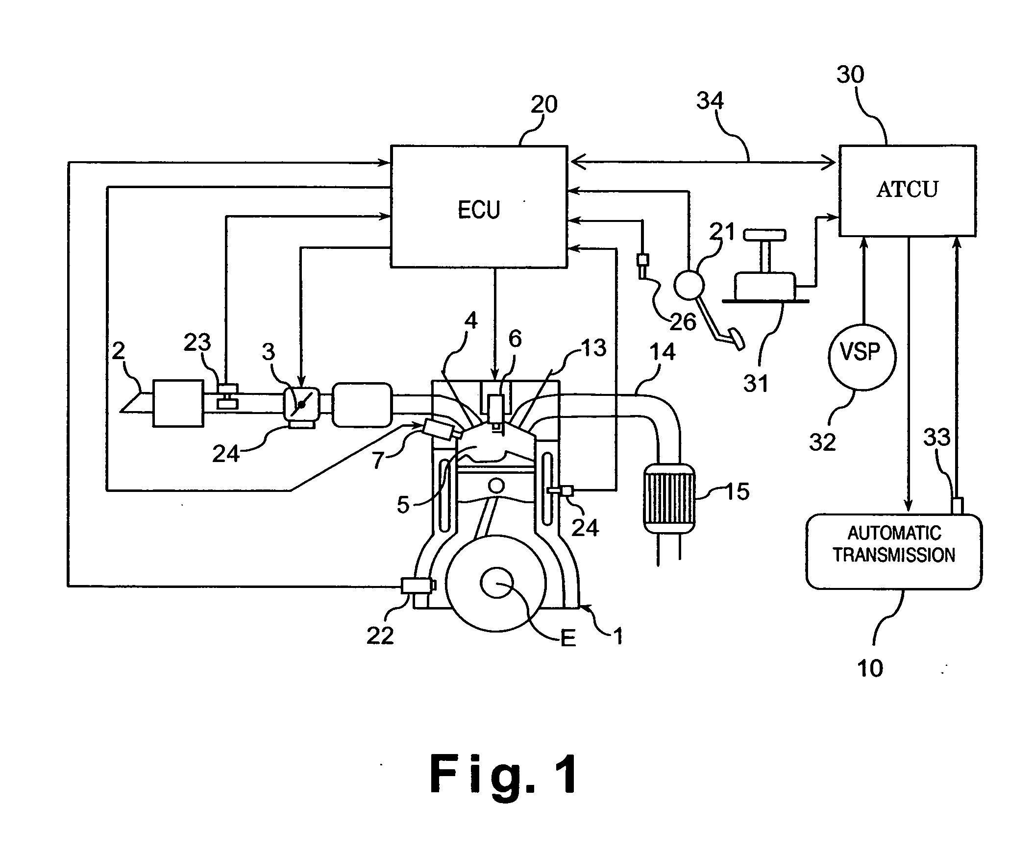
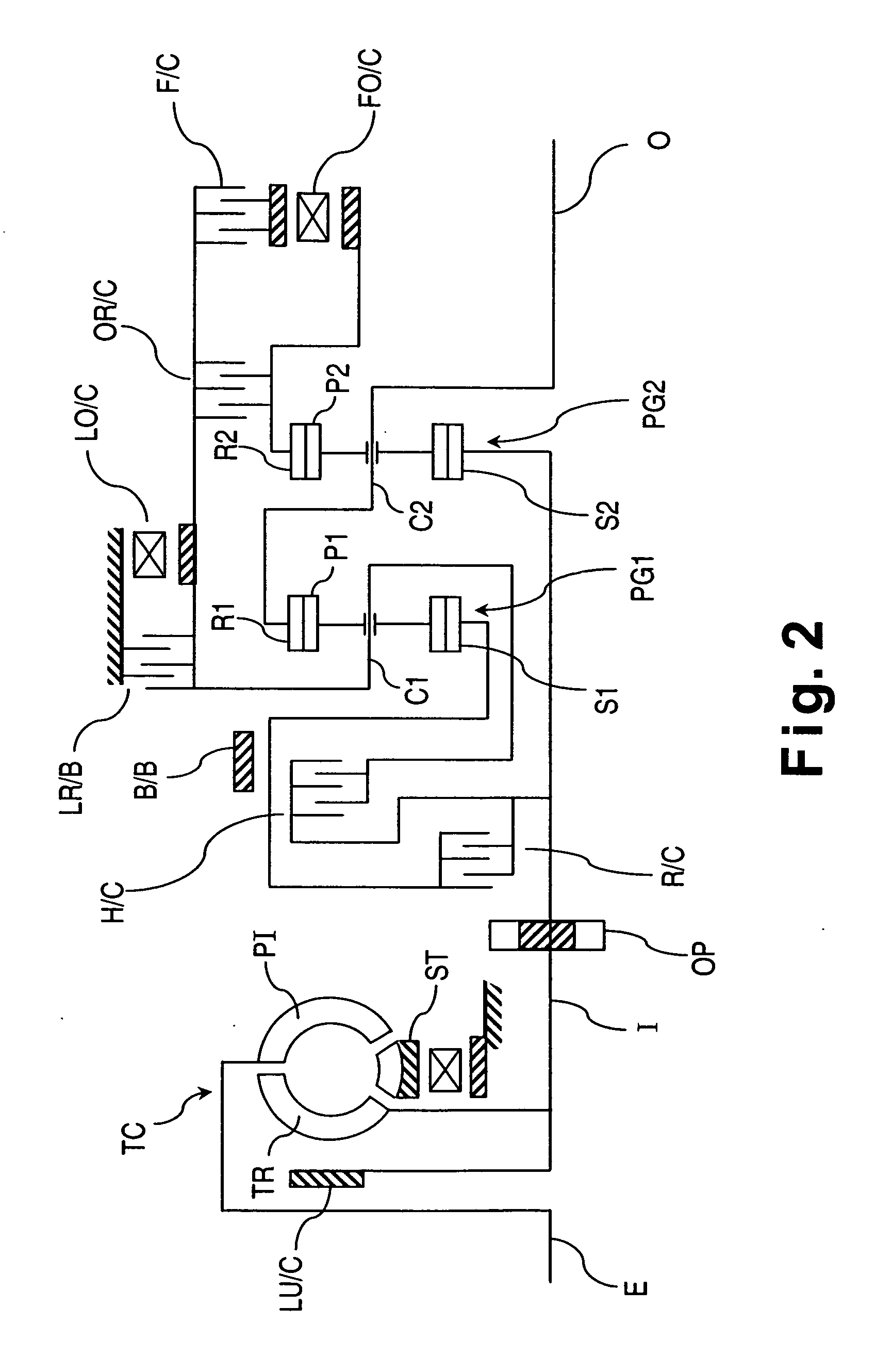
[0093] Referring now to FIGS. 8 and 9, an engine idle speed control device or system in accordance with a second embodiment of the present invention will now be discussed. The schematic structural diagrams illustrated in FIGS. 1 and 2, the table of FIG. 3, the maps of FIG. 6 and the timing charts of FIG. 7 are utilized to understand the engine idle speed control device of the second embodiment of the present invention. Basically, the engine idle speed control device of the second embodiment of the present invention is identical to the first embodiment, except that the control routine of FIG. 4 has been modified to the control routine of FIG. 8. In view of the similarity between the first and second embodiments, the parts or steps of the second embodiment that are identical to the parts or steps of the first embodiment will be given the same reference numerals as the parts of the first embodiment. Moreover, the descriptions of the parts or steps of the second embodiment that are iden...


PUM


Abstract

An engine idle speed control device set a target idle speed NsetN for a non-traveling range is set to a high value to activate the catalytic converter early, after the engine is started. Upon detecting that the automatic transmission has been shifted from a non-traveling range to a traveling range, the target idle speed is lowered to a first traveling idle speed Nset1. A feedback gain G used for feedback control of the ignition timing is then set to a larger gain value. The larger gain value is set such that it varies based on the temperature of the automatic transmission fluid or other parameter indicative of the engine friction and/or automatic transmission friction. As a result, the ignition timing is retarded in a precise manner, the engine speed is reduced, and the clutch engagement shock is reduced.

Description

CROSS-REFERENCE TO RELATED APPLICATIONS [0001] This application claims priority to Japanese Patent Application Nos. 2004-056136 and 2004-056137. The entire disclosures of Japanese Patent Application Nos. Japanese Patent Application Nos. 2004-056136 and 2004-056137 are hereby incorporated herein by reference. BACKGROUND OF THE INVENTION [0002] 1. Field of the Invention [0003] The present invention generally relates to an engine idle speed control device for an internal combustion engine provided with an automatic translation. More specifically, the present invention relates to a device for controlling the idle speed appropriately when the automatic transmission from a non-traveling range to a traveling range. [0004] 2. Background Information [0005] Japanese Laid-Open Patent Publication No. 05-280398 discloses a technology regarding an engine provided with an automatic transmission in which the actual engine speed is adjusted toward a target idle speed based on the difference between ...

Claims


Application Information

Patent Timeline
IPC IPC(8): F02D29/02F02D31/00F02D37/00F02D41/02F02P5/15F16H59/72F16H61/04
CPCB60W2710/065F02D31/003F02D41/0215F02D2250/26F02D2400/12Y10T477/67F02P5/1508F16H59/72F16H2061/0488Y02T10/46F02P5/1504Y02T10/40B60W30/18027
Inventor ISHIKAWA, TSUYOSHIIMAI, ERIKOGA, MASAKI
Owner NISSAN MOTOR CO LTD
Why Eureka
Try Eureka