Formed sheet heat exchanger

a heat exchanger and formed sheet technology, applied in the direction of indirect carbon-dioxide mitigation, lighting and heating apparatus, combustion process, etc., can solve the problems of reducing the efficiency of the turbine, the structure configuration required for such heat exchangers is generally complex, and the heat exchanger is typically labor-intensive, so as to improve the thermal efficiency of the heat exchange and reduce the cost. the effect of heat loss

Inactive Publication Date: 2005-09-01
THE BOEING CO
View PDF18 Cites 40 Cited by
  • Summary
  • Abstract
  • Description
  • Claims
  • Application Information

AI Technical Summary

Benefits of technology

[0007] The present invention provides an apparatus for exchanging heat between fluids. The apparatus includes a plurality of flow divider sheets that are positioned in a stacked configuration to define flow passages therebetween. Each sheet is nonuniform in a longitudinal direction and, in particular, defines a corrugated portion and at least one manifold portion. The corrugated portions of each sheet correspond to the corrugated portions of the adjacent sheets in the stack so that adjacent sheets define fluid channels therebetween in the flow passages. First and second fluids can be delivered through the flow passages, e.g., in an alternating fashion, so that the first and second fluid thermally communicate. The corrugated portions of the sheets can provide relatively large common boundary areas between the fluids in adjacent passages, thereby increasing the thermal efficiency of the heat t

Problems solved by technology

Preburners are sometimes used to heat the incoming airflow via partial combustion, but a preburner can reduce the efficiency of the turbine, and byproducts such as nitrogen oxides and carbon monoxide can be formed in the preburner.
However, the struc

Method used


Image

  • Formed sheet heat exchanger
  • Formed sheet heat exchanger
  • Formed sheet heat exchanger

Examples


Embodiment Construction

[0023] The present invention now will be described more fully hereinafter with reference to the accompanying drawings, in which preferred embodiments of the invention are shown. This invention may, however, be embodied in many different forms and should not be construed as limited to the embodiments set forth herein; rather, these embodiments are provided so that this disclosure will be thorough and complete, and will fully convey the scope of the invention to those skilled in the art. Like numbers refer to like elements throughout.

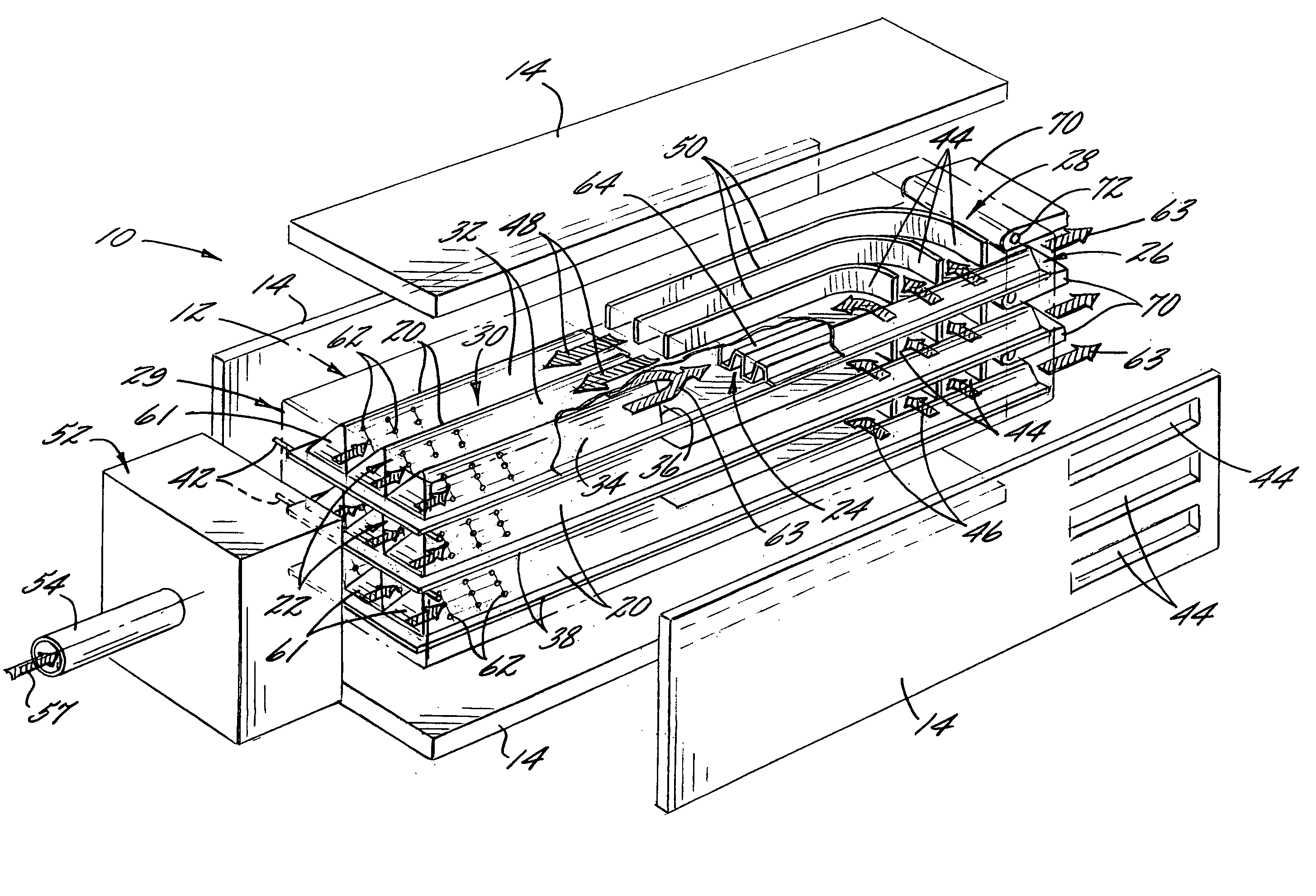
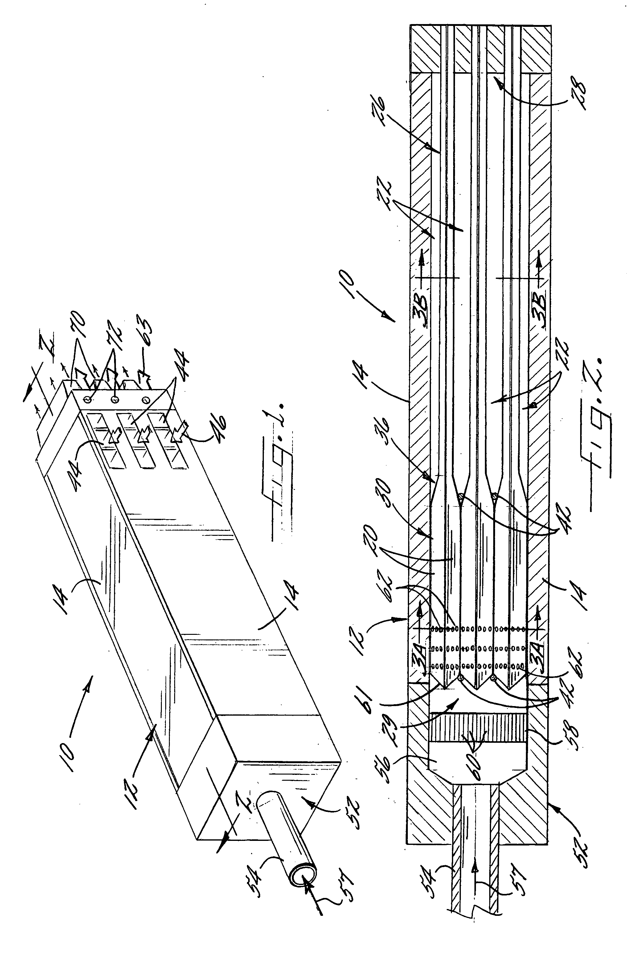
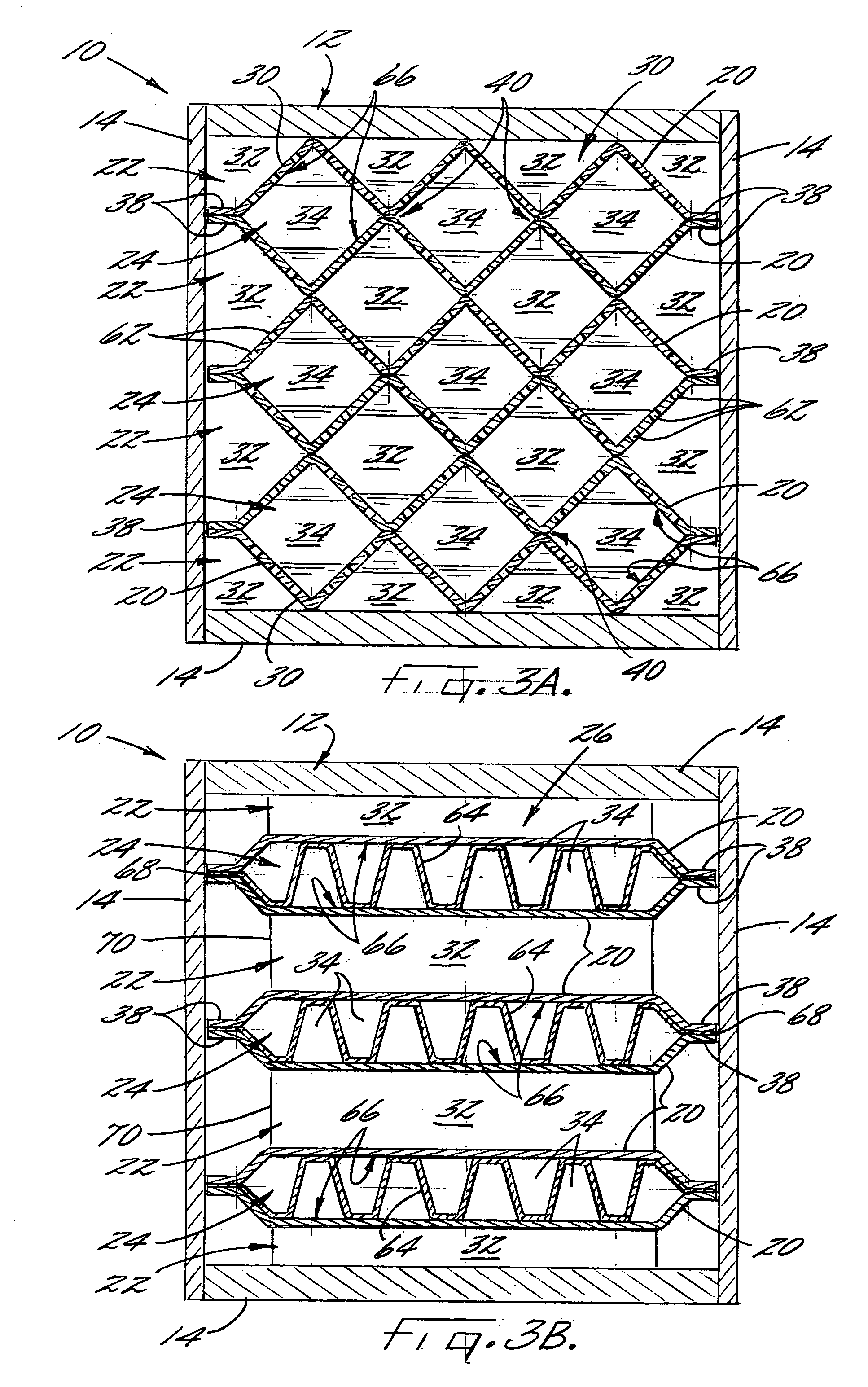
[0024] Referring now to FIG. 1, there is shown a heat exchanging apparatus 10 according to one embodiment of the present invention for transferring thermal energy between first and second fluids. In particular, the apparatus 10 shown in FIG. 1 is a catalytic heat exchanger configured to heat an oxidizing fluid, such as gaseous air, using heat derived from a combustion of a combustible mixture including a gaseous fuel, such as methane, with the air. In ot...


PUM


Abstract

A formed sheet heat exchanger is provided for exchanging heat between fluids is provided. The apparatus includes flow divider sheets that are positioned in a stacked configuration and extend in a longitudinal direction so that adjacent pairs of the sheets define flow passages therebetween for receiving first and second fluids. Each of the sheets is nonuniform in the longitudinal direction, having a manifold portion and a corrugated portion. The corrugated portions of each adjacent pair of sheets define a plurality of fluid channels therebetween that are connected to the portion of the flow passage defined between the manifold portions. The fluid channels are configured to receive the first or second fluids and transfer thermal energy therebetween through the flow divider sheets.

Description

BACKGROUND OF THE INVENTION [0001] 1) Field of the Invention [0002] The present invention relates to apparatuses and methods for exchanging heat between fluids and, more particularly, to a counter-flow heat exchanger with passages defined by nonplanar sheets. [0003] 2) Description of Related Art [0004] Heat exchangers, which are used in numerous applications and industries, generally define two sets of passages that are at least substantially fluidly disconnected. A relatively hot fluid flows through a first set of passages of the heat exchanger, and a relatively cool fluid flows through a second set of passages of the exchanger. The two sets of passages thermally communicate so that thermal energy is transferred from the hot fluid to the cool fluid. The fluids can flow in the same direction, perpendicular directions, or opposite directions. Heat exchangers characterized by opposite flow of the fluids are typically referred to as counter-flow devices. [0005] One application for whic...

Claims


Application Information

Patent Timeline
IPC IPC(8): F28D9/00F28F3/02
CPCF23L15/00F28F9/026F28F3/025F28D9/0031F28F2250/104Y02E20/34
Inventor FOWSER, SCOTT W.HORN, MARK D.STRAUB, ANDREAS C.WAGNER, JON C.
Owner THE BOEING CO
Why Eureka
Try Eureka