Self-pumping hydropneumatic suspension strut unit

a technology of hydropneumatic suspension and strut unit, which is applied in the direction of positive displacement liquid engine, machine/engine, shock absorber, etc., can solve the problems of working cylinder loss of pretensioning force, change in overall length of the unit, and loose work itself, etc., to achieve optimal utilization of the stroke of the rod, simple and low cost

Inactive Publication Date: 2005-09-01
ZF FRIEDRICHSHAFEN AG
View PDF9 Cites 9 Cited by
  • Summary
  • Abstract
  • Description
  • Claims
  • Application Information

AI Technical Summary

Benefits of technology

[0005] An object of the invention is to create a simple and low-cost pump rod attachment, which is short in order to ensure optimal utilization of the stroke of the rod and which at the same time keeps the pump rod and the working cylinder under pretension regardless of the operating conditions.

Problems solved by technology

During operation of a suspension strut unit of this type, it has been found that changes in the overall length of the unit occur as a result of fluctuations in temperature and pressure.
As a result of such changes, the working cylinder can lose its pretensioning force, and the slotted disk, because of the lack of elasticity of the associated components, can work itself loose.
The disadvantage here is not only that noise can develop but also that, under certain conditions, a decrease in the damping pressure can occur in the suspension spring strut unit.

Method used


Image

  • Self-pumping hydropneumatic suspension strut unit
  • Self-pumping hydropneumatic suspension strut unit
  • Self-pumping hydropneumatic suspension strut unit

Examples


Embodiment Construction

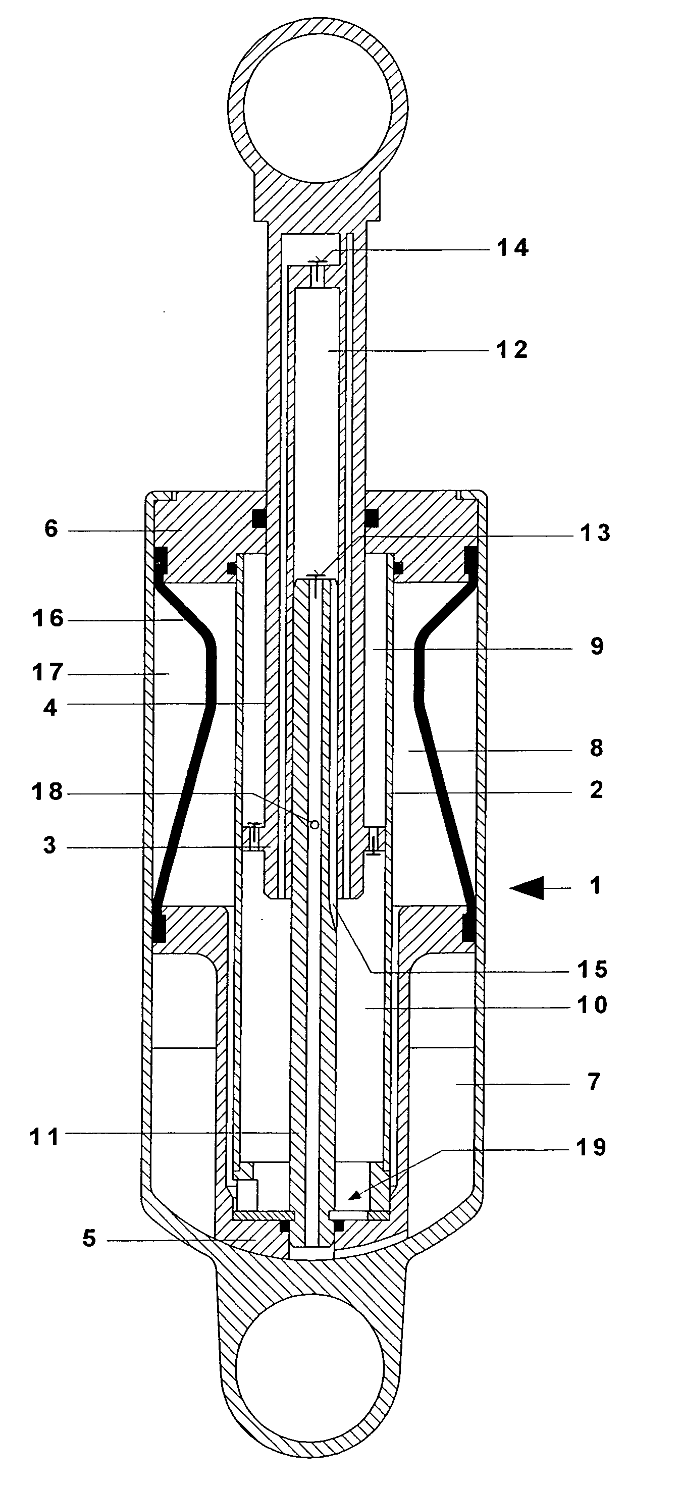
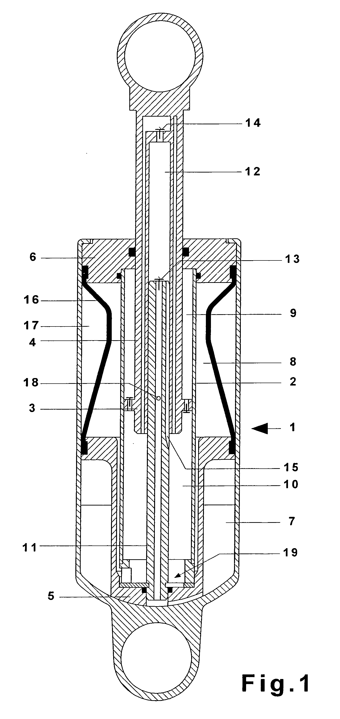
[0021] The self-pumping hydropneumatic suspension strut unit 1 for motor vehicles shown in FIG. 1 consists essentially of the working cylinder 2, in which a damping piston 3, mounted at the end of a hollow piston rod 4, slides. The working cylinder 2 is closed off at one end by an end wall 5 and at the other end by the rod guide 6, through which the hollow piston rod 4 extends to the outside with the help of a seal. By way of the end wall 5, the spring strut unit is attached by means of a fastening eye to the body of the vehicle, and at the lower end of the spring strut unit, the piston rod 4 is attached by means of another mounting eye to the axle of the vehicle in a manner not shown. The working cylinder 2 is surrounded by a ring-shaped, partially oil-filled, partially gas-filled compensating chamber, which is divided by an intermediate wall into a high-pressure chamber 8 and a low-pressure chamber 7. A high-pressure gas cushion 17 in the high-pressure chamber 8 is separated from ...


PUM


Abstract

Self-pumping hydropneumatic suspension strut unit with internal level control, with an oil-filled working cylinder subject to the pressure of gas cushions and with a damping piston, which is free to slide inside the cylinder and is mounted at the end of a hollow piston rod, the cavity of which serves as a pump cylinder for a pump rod attached to the working cylinder. Oil is drawn from a reservoir space when the piston rod travels outward, whereas the oil is conveyed into the working space when the piston rod travels inward. The pump rod passes through the end wall of the working space and is held axially in position by an end-mounted disk, which acts as a universal joint for the rod, and the disk engages in a groove in the pump rod and is held in place by its outer circumference axially between the working cylinder and the end wall of the working cylinder. The disk has a slot to accept the pump rod, the first area of this slot having a diameter corresponding to the base of the groove, whereas the second area has a diameter corresponding to the outside diameter of the pump rod.

Description

BACKGROUND OF THE INVENTION [0001] 1. Field of the Invention [0002] The invention pertains to a self-pumping hydropneumatic suspension strut unit with internal level control, with an oil-filled working cylinder subject to the pressure of gas cushions and with a damping piston, which is free to slide inside the cylinder and is mounted at the end of a hollow piston rod, the cavity of which serves as a pump cylinder for a pump rod attached to the working cylinder. Oil is drawn from a reservoir space when the piston rod travels outward, whereas the oil is conveyed into the working space when the piston rod travels inward. The pump rod passes through the end wall of the working space and is held axially in position by an end-mounted disk, which acts as a universal joint for the rod. The disk engages in a groove in the pump rod and is held in place by its outer circumference axially between the working cylinder and the end wall of the working cylinder. [0003] 2. Description of the Related...

Claims


Application Information

Patent Timeline
Patent Type & Authority Applications(United States)
IPC IPC(8): B60G15/12B60G17/044F04B1/26F16F9/06F16F9/56
CPCB60G17/044B60G15/12
Inventor BECK, HUBERTKUCHHEUSER, WERNER
Owner ZF FRIEDRICHSHAFEN AG
Why Eureka
Try Eureka