Heater mat made of electrically-conductive fibers

a technology of electrically conductive fibers and heaters, which is applied in the direction of heating element materials, heating element shapes, heating elements, etc., can solve the problems of affecting the performance of the aircraft,

Active Publication Date: 2005-09-01
EUROCOPTER
View PDF2 Cites 46 Cited by
  • Summary
  • Abstract
  • Description
  • Claims
  • Application Information

AI Technical Summary

Benefits of technology

[0012] An object of the present invention is to provide a heater mat for aerodynamic surfaces, which mat is made of a resistor element that enables the above-mentioned limitations to be overcome.
[0016] In addition, this configuration also makes it possible to obtain better control over the local orientation of the electrically-conductive fibers, thereby avoiding the implementation difficulties that are to be found in devices prior to the invention.

Problems solved by technology

This super-cooled state is a state of highly unstable equilibrium that can be disrupted if some very small quantity of energy is delivered to the water droplet, e.g. in the form of a mechanical impact.
This deposit of ice increases the weight of the aircraft, sometimes to a considerable extent, and interferes with the air flow by changing the shape of the aerodynamic surface, thereby greatly degrading its performance.
The formation of hard ice, soft ice, or frost leads to weight overload, increases drag CD of the aerodynamic surface, and reduces its lift CL.
Nevertheless, cutting out, laying, and assembling such resistive layers made of electrically-conductive carbon fibers impregnated in a thermosetting organic matrix raise several manufacturing problems because of the complexity involved.
That complex architecture requires a large amount of cutting-out to be performed which is economically penalizing.
Furthermore, the orientation of the longitudinal and transverse tapes must be accurately laid out, so the time required for manual draping of all the pieces turns out to be long.
Furthermore, the surface quality of the longitudinal and transverse tapes in a given resistive layer (contact area, local orientation of fibers), which is essential for proper operation of the resistive array as a whole, is not always effectively guaranteed.
It can happen that dielectric plastic separators are forgotten during assembly resulting in the part being rejected.

Method used


Image

  • Heater mat made of electrically-conductive fibers
  • Heater mat made of electrically-conductive fibers

Examples


first embodiment

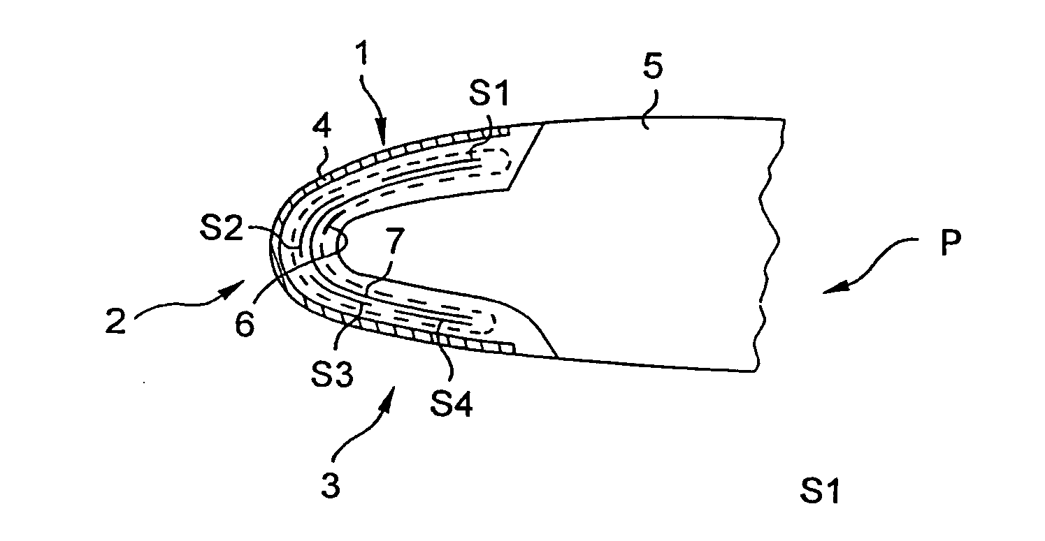
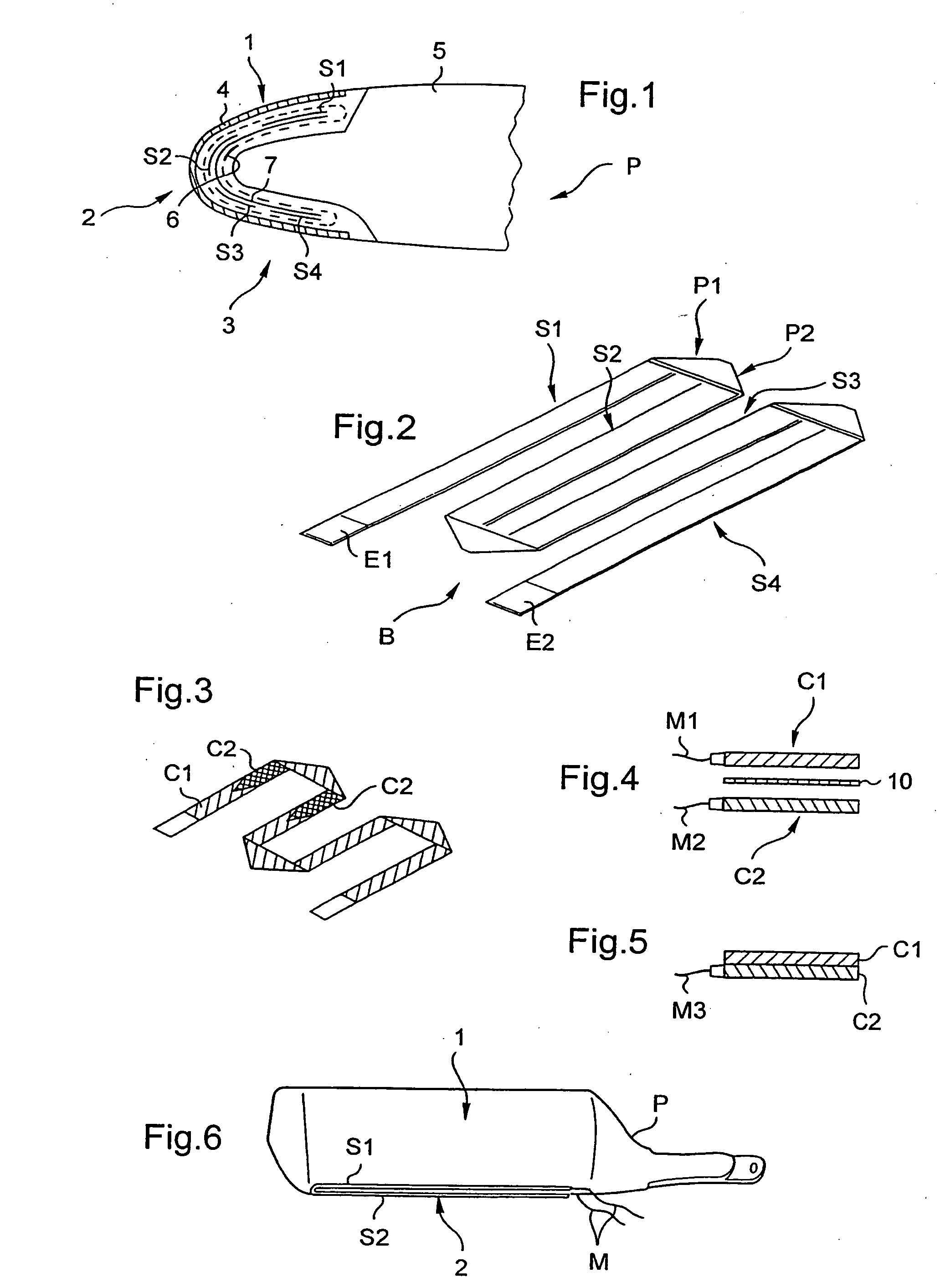
[0032]FIG. 2 shows a resistor element in a This resistor element is said to be a “single layer” element insofar as it has only one strip B of electrically-conductive fibers, e.g. carbon fibers.

[0033] This single strip B is made up of four substantially parallel segments S1, S2, S3, and S4. Adjacent segments S1 and S2 come from a portion of the single strip B, this portion being folded in two zones P1 and P2. Similarly, two folds are made between the adjacent segments S2 and S3, and two more folds between the adjacent segments S3 and S4. Depending on the desired configuration, a larger number of folds could be made between two adjacent segments.

[0034] The ends E1 and E2 of the single strip B enable the strip to be connected to the electrical power supply means of the aircraft. By being powered electrically in continuous manner during a flight by the electrical power means of the aircraft, the resistor element acts in anti-icing mode. The aerodynamic surface is heated by the Joule e...

second embodiment

[0035]FIG. 3 shows a resistor element in a This heater mat is said to be “multilayer” insofar as it comprises two superposed resistive layers C1 and C2.

[0036] The first and second resistive layers C1 and C2 are each constituted by a single strip of electrically-conductive fibers, each single strip being folded on the same principles as described above. The single strip of the first resistive layer C1 is of constant width. One portion of the single strip constituting the second resistive layer C2 is of constant width, whereas its other two portions are of continuously varying width.

[0037] In a first variant of the second embodiment, shown in FIG. 4, the first and second resistive layers C1 and C2 are superposed and adjacent. In addition, they are separated by a dielectric layer 10. Advantageously, the dielectric layer is made up of a glass fabric impregnated in the same thermosetting impregnation matrix as the matrix impregnating the electrically-conductive fibers of the first and ...


PUM


Abstract

A heater mat for using the Joule effect to heat an aerodynamic surface. The heater mat is provided with a resistor element including at least two substantially parallel segments of electrically-conductive fibers disposed on the aerodynamic surface. The segments come from a single strip of electrically-conductive fibers, with two adjacent segments being obtained by folding a portion of the single strip at least twice.

Description

[0001] The present invention relates to a heater mat for heating aerodynamic surfaces of an aircraft. More particularly, the aerodynamic surfaces in question are those having an aerodynamic shape that must not be disturbed by ice forming thereon, such as, in particular: the blades of the main rotor or the tail rotor of a rotorcraft, or the wings of an airplane. [0002] More generally, the invention may also advantageously be used for de-icing and / or anti-icing of structures in which weight overload due to ice could severely degrade mechanical performance, or efficiency, such as the blades of wind turbines, the air inlets of engines, Fenestron® type ducted rotors (walls for guiding the air feed stream, blades), and even the fuselages of aircraft. BACKGROUND OF THE INVENTION [0003] The problem of aerodynamic surfaces icing is well known in the aviation industry. The term “icing” is used to designate the more or less rapid build-up of a deposit of ice on certain portions of an aircraft ...

Claims


Application Information

Patent Timeline
Patent Type & Authority Applications(United States)
IPC IPC(8): B64D15/12
CPCB64D15/12
Inventor BRUNNER, DANIELAMARI, ANDRE
Owner EUROCOPTER
Why Eureka
Try Eureka