Glove inverter

a glove and inverter technology, applied in the field of glove inverters, can solve the problem of adding an additional component to manufactur

Active Publication Date: 2005-09-01
SMITH GREGORY J +1
View PDF29 Cites 7 Cited by
  • Summary
  • Abstract
  • Description
  • Claims
  • Application Information

AI Technical Summary

Problems solved by technology

Moreover it incurs an added expense to manufacture an additional component.

Method used


Image

  • Glove inverter
  • Glove inverter

Examples


Embodiment Construction

[0023] Further characteristics and advantages according to the present invention will become apparent from the following detailed description of a preferred but not exclusive embodiment thereof.

[0024] The glove appendage-inverting device of the present invention is especially, but not exclusively, for industrial, heavy duty, lined, rubber-gloves. It can also be used with any thick material glove, such as ski gloves, leather gloves, semi-rubber gloves etc.

[0025] The present invention allows for the trouble free and expeditious inversion of glove appendages thereby facilitating efficient cleaning and subsequent rapid drying thereof.

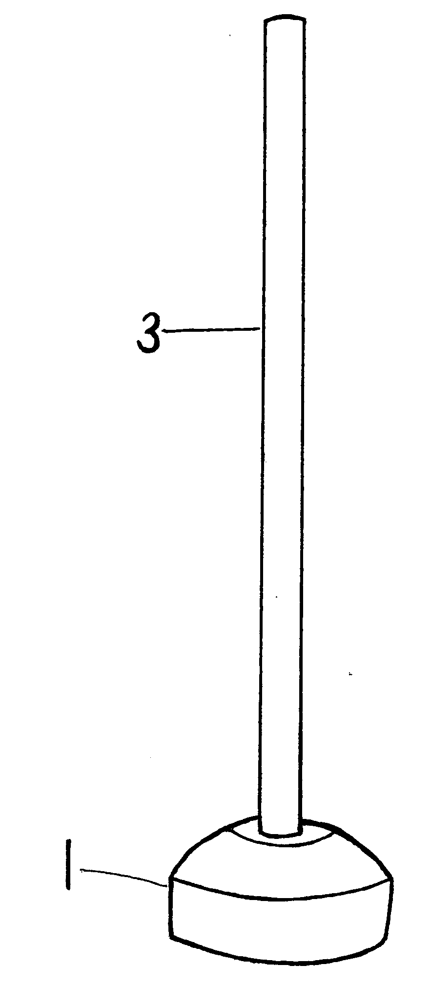
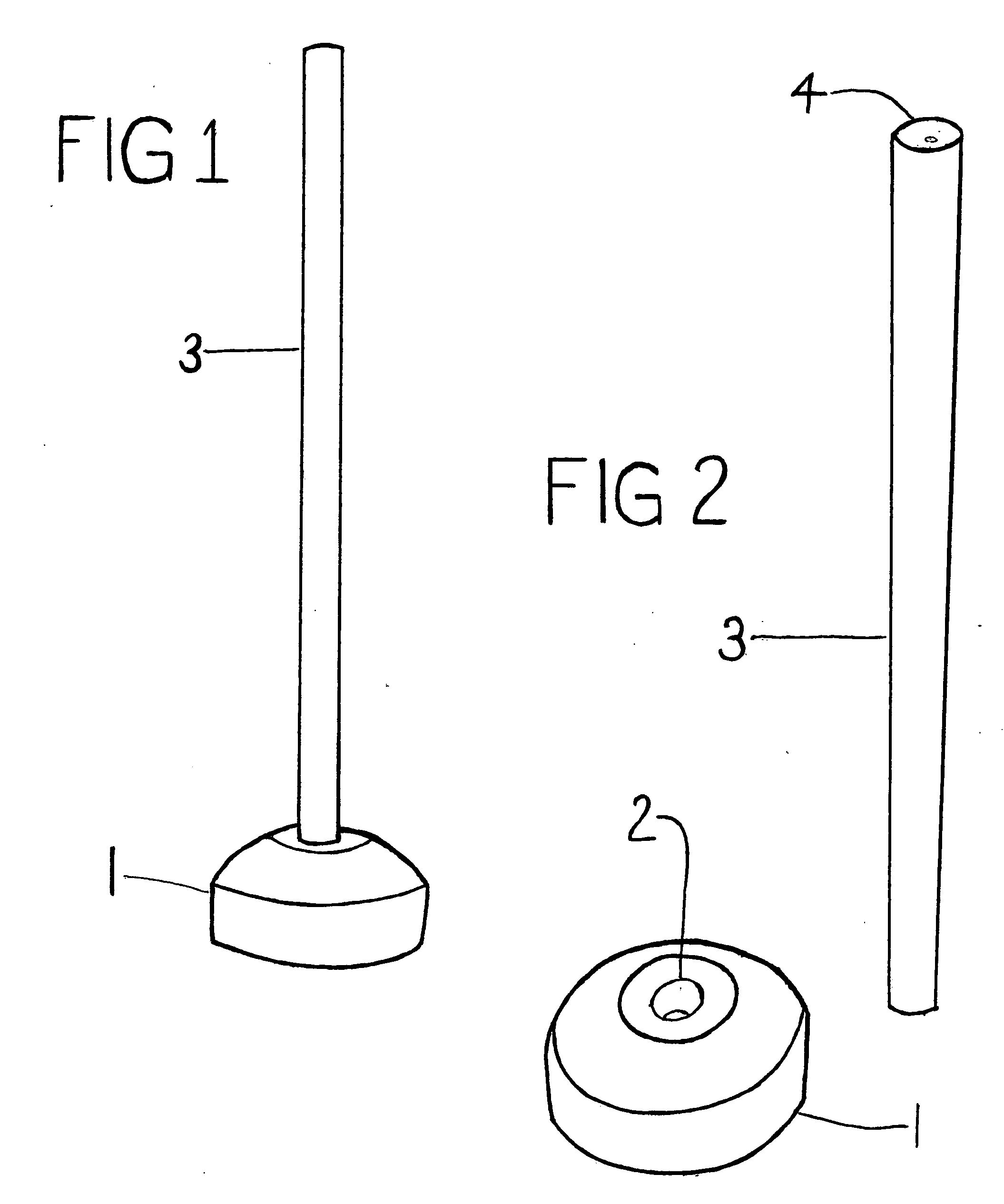
[0026] The present invention consists of a small portable base (1) that has an opening (2) with a depth sufficient to receive and stabilize a pushrod (3) and a pushrod (3), the tip of which is concave (4) opposite to the end that fits into the opening (2) in the base (1).

[0027] The base (1) is a small-semi-circular shape that fits comfortably in the pal...


PUM


Abstract

The present invention is a device that provides a trouble free method to invert glove appendages expeditiously; especially but not exclusively, industrial, heavy duty, lined, rubber gloves; to facilitate efficient cleaning and subsequent rapid drying of the lining, which consists of a base that has a cavity and a pushrod that fits into the cavity in the base to be securely mounted therein, wherein the exposed cavity in the tip of the pushrod engages the tip of the glove appendage insuring continuous contact between the tip of the pushrod and the glove appendage tip while the glove is peeled down over the pushrod, thereby accomplishing complete inversion of the glove appendage.

Description

FEDERALLY SPONSORED RESEARCH [0001] Not Applicable SEQUENCE LISTING OR PROGRAM [0002] Not Applicable BACKGROUND [0003] 1. Inception of Invention [0004] The inception of this invention arose from my personal experience in the Pearl and Construction industry in Japan. I spent too much of my break time turning rubber gloves inside out by hand to clean and dry them. I discontinued this practice because it was too frustrating and time consuming, and as a result, I began to have serious health problems with my hands including redness, itching, chaffing, etc. not to mention the stress accompanying such discomfort I searched for a device to invert rubber gloves at numerous outlets that cater to industries utilizing industrial, heavy duty, lined, rubber gloves; but to no avail. [0005] 2. Technical Field [0006] The present invention relates to inverting glove appendages, especially but not limited to industrial, heavy duty, lined, rubber gloves. It can also be used for any thick material glov...

Claims


Application Information

Patent Timeline
Patent Type & Authority Applications(United States)
IPC IPC(8): A41D19/04A41H43/00A47G25/80
CPCA41D19/043
Inventor SMITH, GREGORY JOHN
Owner SMITH GREGORY J
Why Eureka
Try Eureka