Method of making sputtering target

a sputtering target and target technology, applied in the field of making sputtering targets, can solve the problems of disadvantageous sintering and roll process, cip sputtering target made using the cip process,

Active Publication Date: 2005-09-01
HOWMET CORPORATION
View PDF6 Cites 82 Cited by
  • Summary
  • Abstract
  • Description
  • Claims
  • Application Information

AI Technical Summary

Benefits of technology

[0005] In another illustrative embodiment of the present invention, a method is provided for making a billet or bar comprising molybdenum (Mo) for a sputtering target wherein two or more sintered powder metal bodies comprising Mo are diffusion bonded together at one or more metal-to-metal joints therebetween in a first hot isostatic pressing operation to form a preform. Two or more preforms then are placed adjacent one another (e.g. stacked one on the other) with a powder metal layer comprising Mo present at joints between the adjacent preforms. The adjacent preforms are hot isostactically pressed in a second hot isostatic pressing operation to form a diffusion bond at each metal-to-powder metal layer-to-metal joint between adjacent preforms to form a billet or bar that can be machined or otherwise formed to provide a large sputtering target. The number and dimensions of the preforms placed adjacent one another are selected to yield a desired large size the billet or bar suitable for the sputtering target.
[0007] Other advantages, features, and embodiments of the present invention will become apparent from the following description.

Problems solved by technology

Mo sputtering targets made using the CIP, sinter and roll process are disadvantageous due to the sputter yield of the target and of the etching characteristics of the deposited thin film.

Method used


Image

  • Method of making sputtering target
  • Method of making sputtering target
  • Method of making sputtering target

Examples


Embodiment Construction

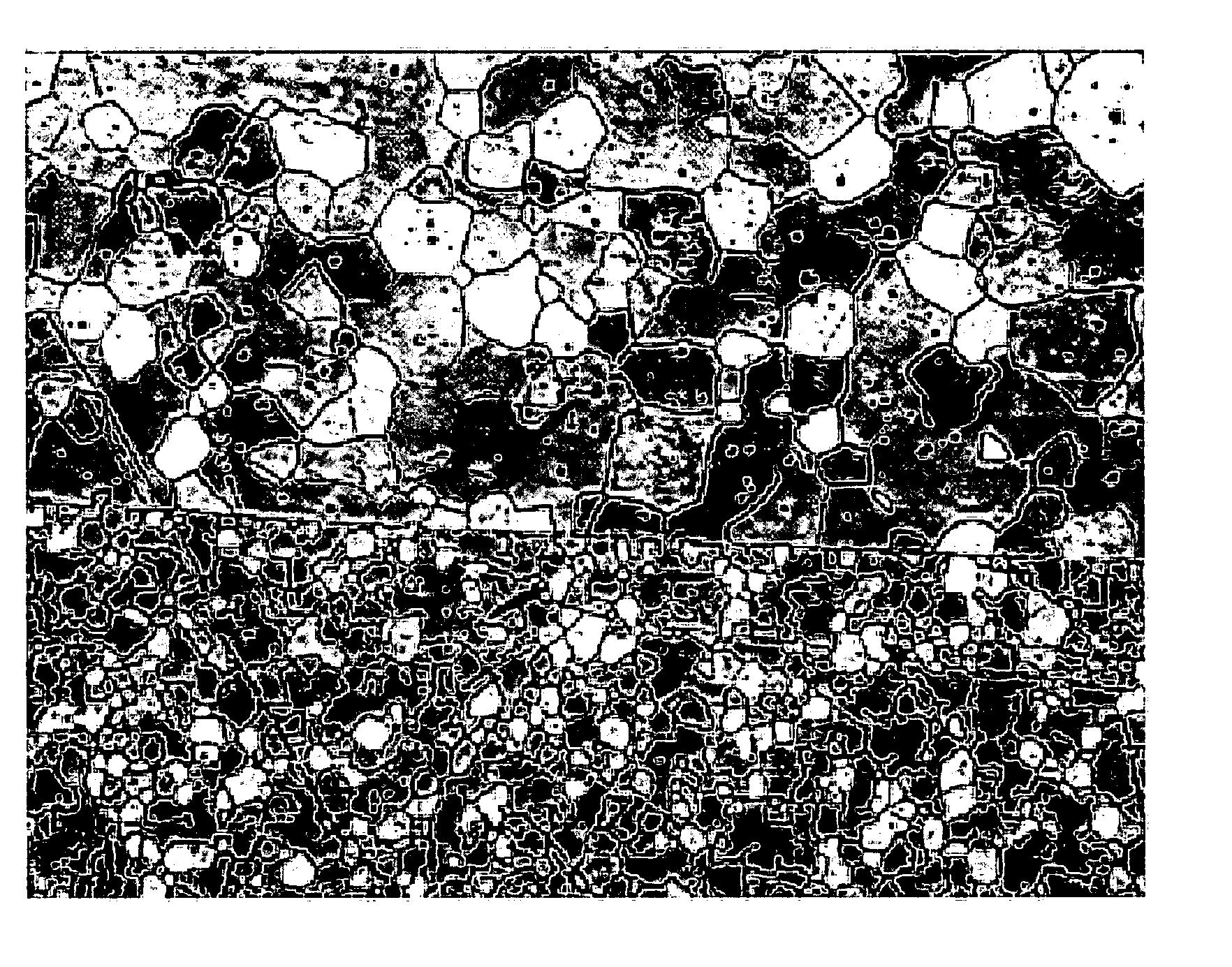
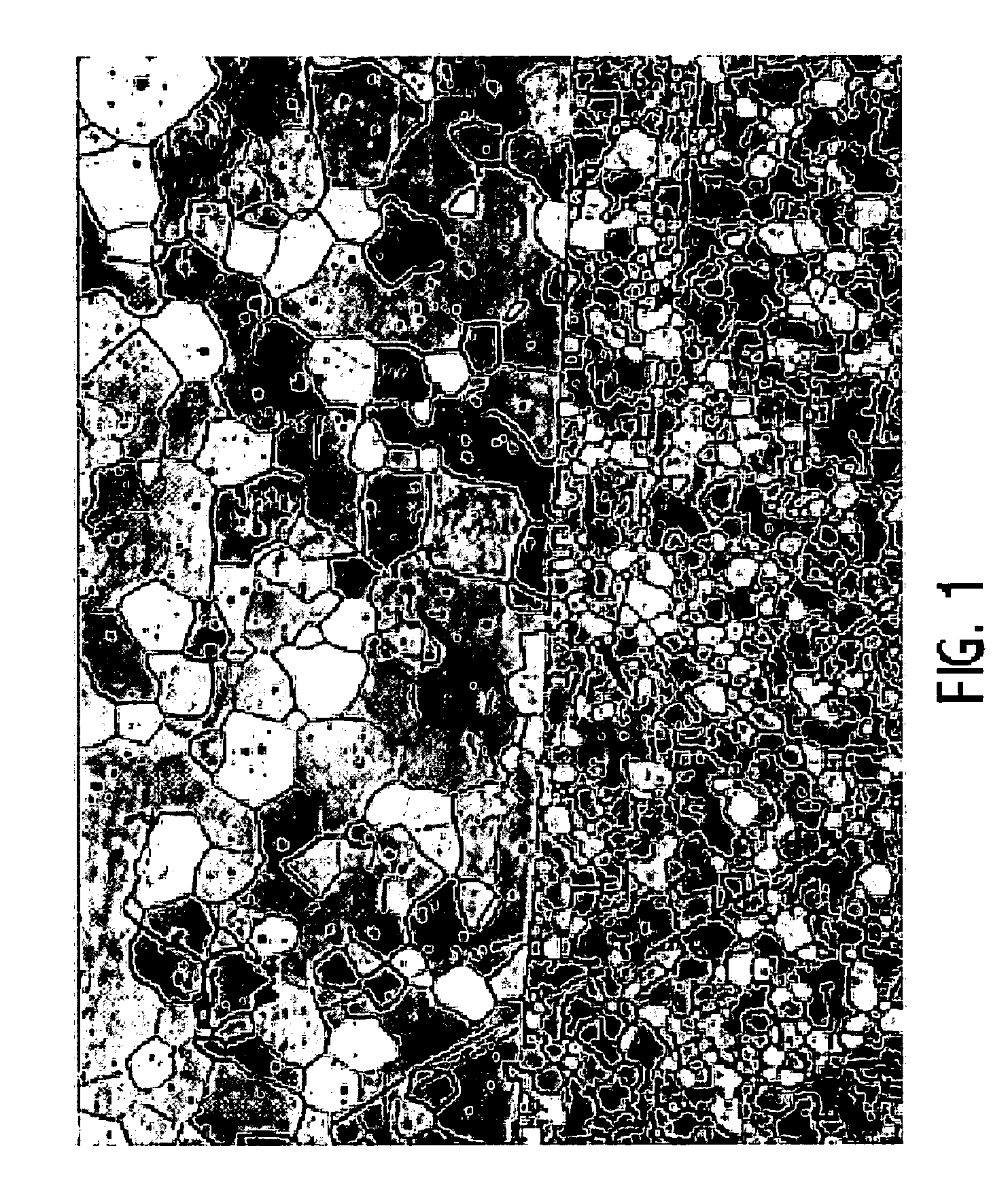
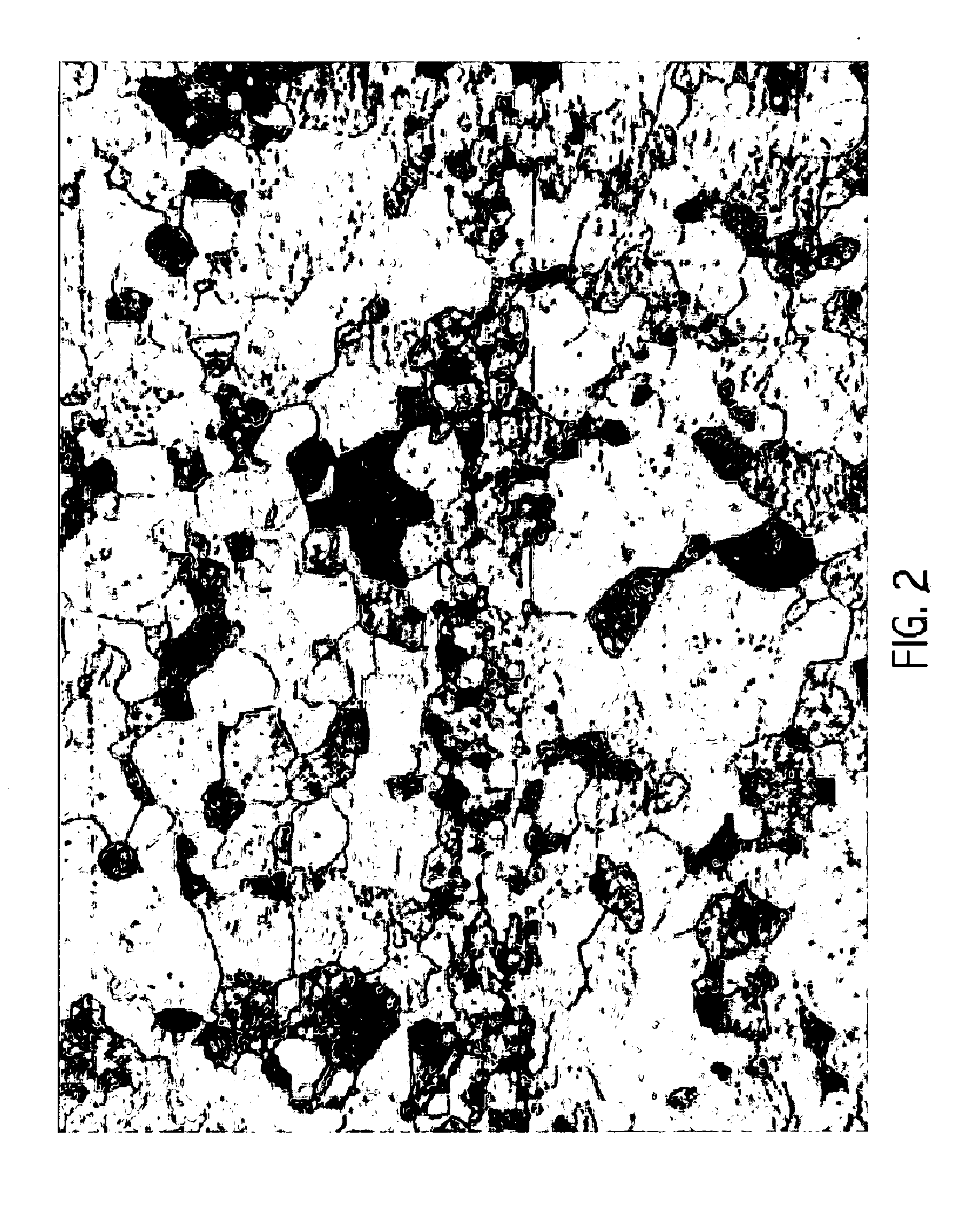
[0010] The present invention provides a method of making an elongated body, such as a large billet or bar, comprising molybdenum (Mo) for a sputtering target. For purposes of illustration and not limitation, the method can be used to make a billet or bar for the sputtering target having a bar length of 3000 mm and above and bar cross-sectional dimensions of 225 mm by 225 mm (mm is millimeters) and less, although practice of the invention is not limited to any particular size billet / bar as any size may be made suitable for an intended target application. The billet or bar for the sputtering target exhibits a microstructure comprising equiaxed grains of desired small grain size (e.g. about 30 microns or less) and exhibits a low oxygen content of less than about 100 ppm (part per million by weight) as explained below. The billet or bar for the sputtering target includes a density of greater than 99% of theoretical density.

[0011] An illustrative embodiment of the method of the inventio...


PUM

PropertyMeasurementUnit
grain sizeaaaaaaaaaa
lengthaaaaaaaaaa
lengthaaaaaaaaaa

Abstract

A method of making a large Mo billet or bar for a sputtering target wherein two or more bodies comprising Mo are placed adjacent one another (e.g. stacked one on the other) with Mo powder metal present at gaps or joints between the adjacent bodies. The adjacent bodies are hot isostatically pressed to form a diffusion bond at each of the metal-to-Mo powder layer-to-metal joint between adjacent bodies to form a billet or bar that can be machined or otherwise formed to provide a large sputtering target. The number and dimensions of the Mo bodies placed adjacent one another are selected to yield a desired large size the billet or bar suitable for the sputtering target. The billet or bar for the sputtering target exhibits a microstructure comprising equiaxed grains of less than 30 microns grain size and exhibits a low oxygen content of less than about 100 ppm by weight.

Description

[0001] This application claims benefits and priority of provisional application Ser. No. 60 / 548,790 filed Feb. 27, 2004, and provisional application Ser. No. 60 / 603,528 filed Aug. 20, 2004.FIELD OF THE INVENTION [0002] The present invention relates to a method of making a large billet or bar comprising molybdenum (Mo) for a sputtering target and to the billet and sputtering target produced by the method. BACKGROUND OF THE INVENTION [0003] The current method of making a large molybdenum sputtering target is to cold isostatic press (CIP) Mo powder, sinter to reduce the oxygen content and then hot roll to a plate length / width / thickness desired. The plate then is machined to final tolerance. Mo sputtering targets made using the CIP, sinter and roll process are disadvantageous due to the sputter yield of the target and of the etching characteristics of the deposited thin film. This is related to the plate microstructure that is formed during the rolling process. SUMMARY OF THE INVENTION ...

Claims


Application Information

Patent Timeline
Patent Type & Authority Applications(United States)
IPC IPC(8): B23K20/00B23K20/02B23K28/00C23C14/34C23C14/35
CPCC23C14/3414B23K20/021
Inventor BUTZER, GREG A.HUIZENGA, ROBERT H.MUSSMAN, STEVEN D.
Owner HOWMET CORPORATION
Why Eureka
Try Eureka