
EMI suppression in permanent magnet DC motors having PCB outside motor in connector and overmolded

a permanent magnet dc motor and pcb technology, applied in the field of electromagnetic interference suppression of dc motors, can solve the problems of significant emi generation of dc brush motors

Inactive Publication Date: 2005-09-01
BROSE FAHRZEUGTEILE GMBH & CO KG HALLSTADT (DE)
View PDF20 Cites 16 Cited by
  • Summary
  • Abstract
  • Description
  • Claims
  • Application Information

AI Technical Summary

Benefits of technology

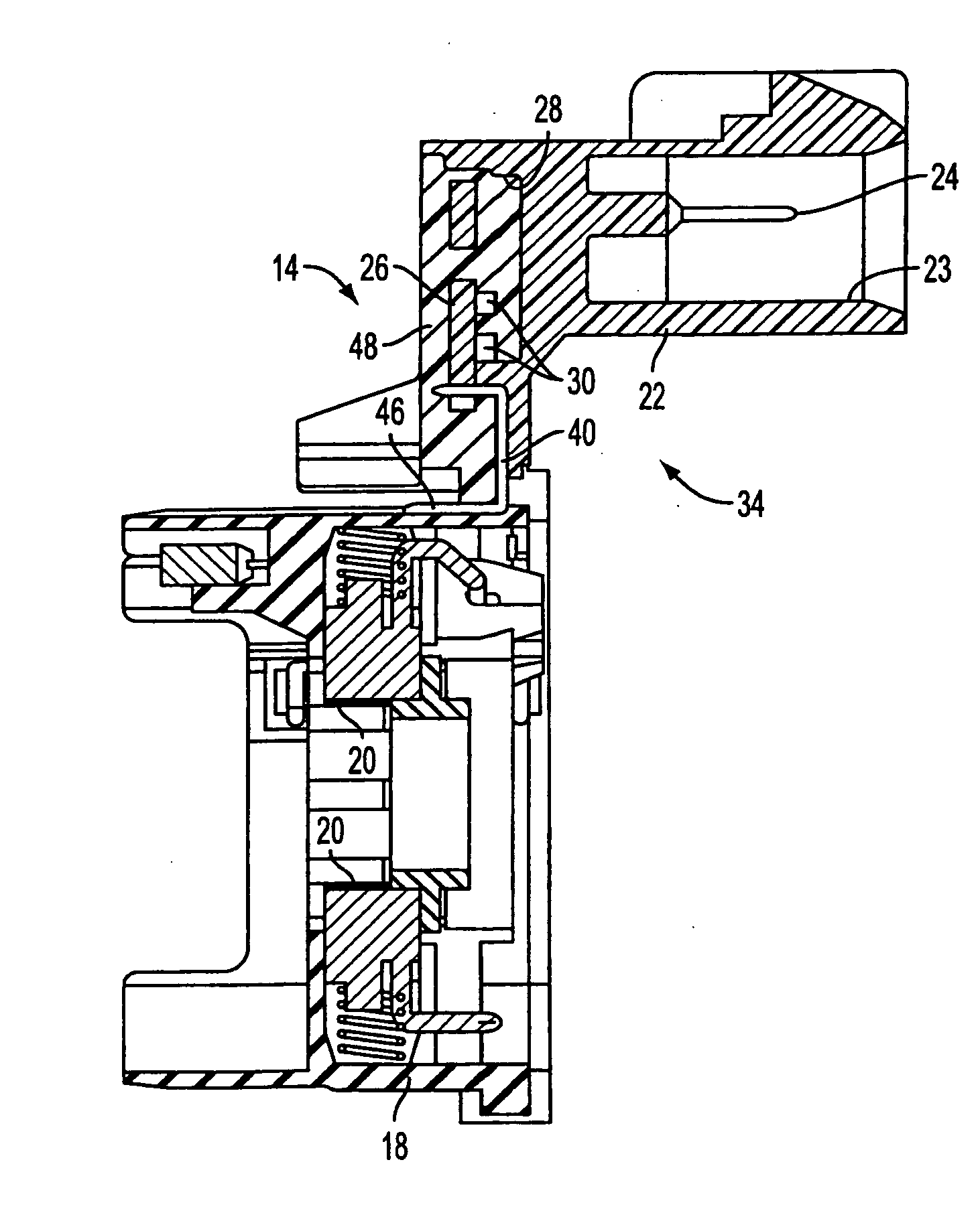
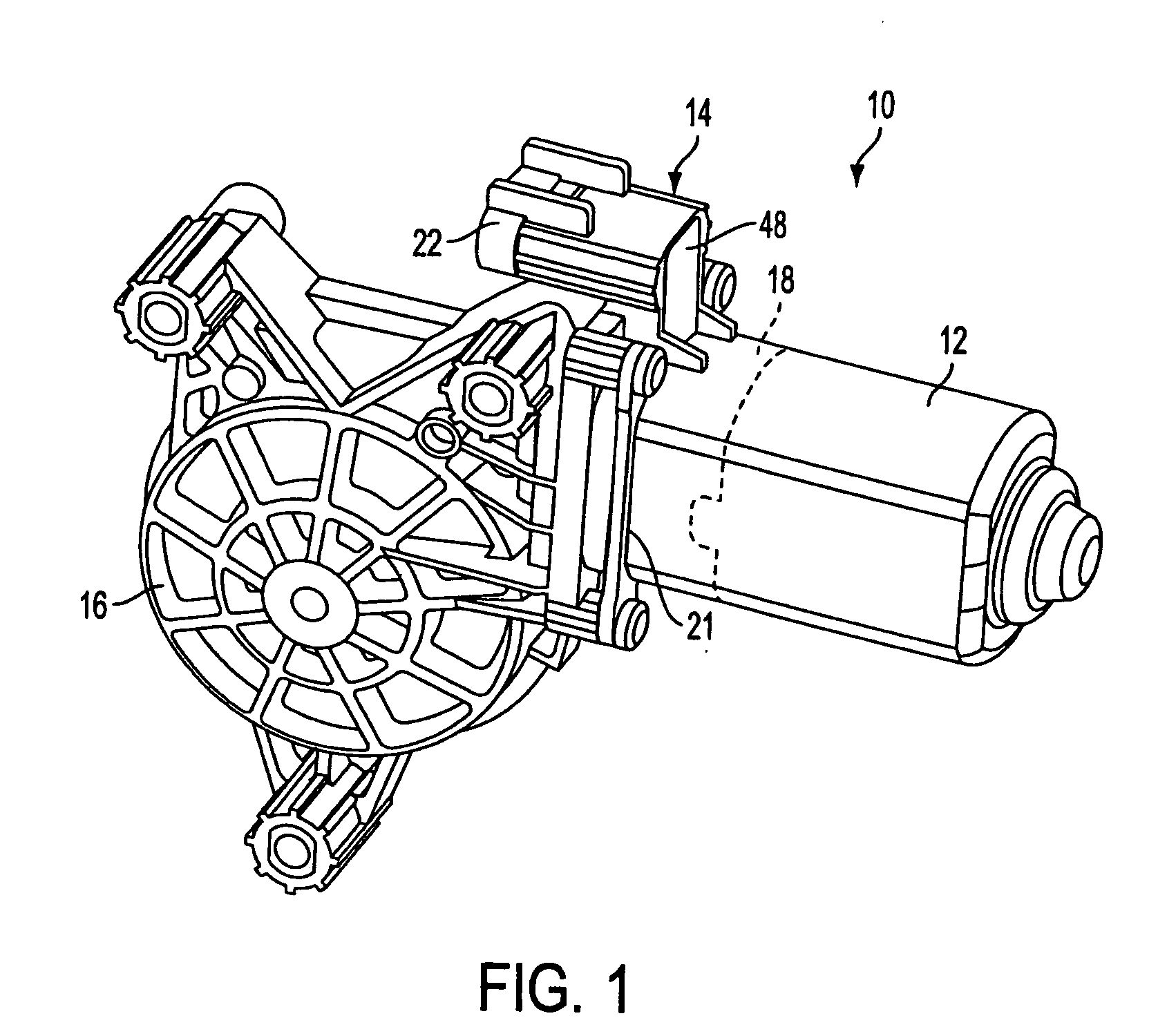
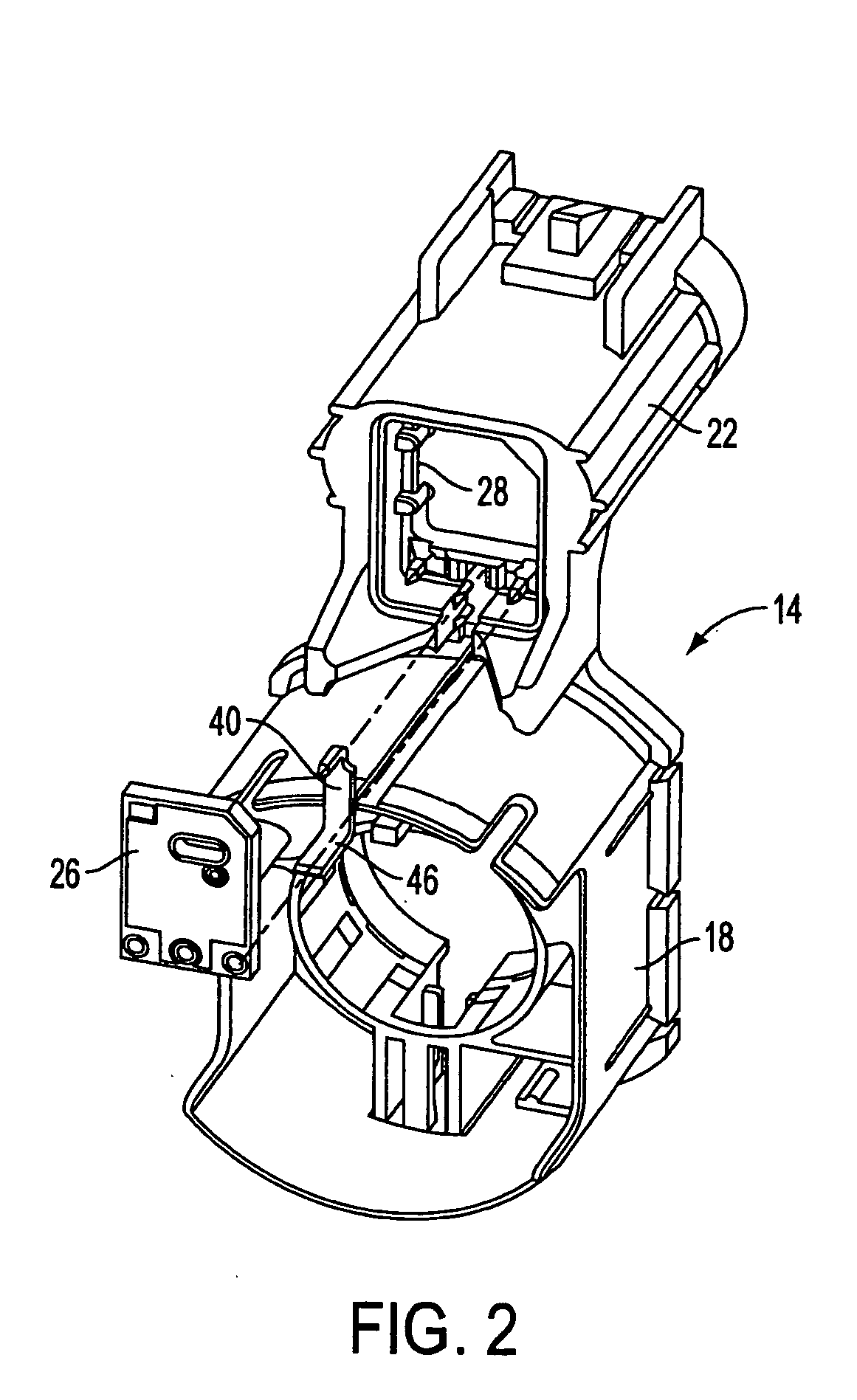
[0005] An object of the present invention is to fulfill the need referred to above. In accordance with the principles of the present invention, this objective is obtained by providing a permanent magnet DC motor having electro-magnetic interference (EMI) suppression includes a metal motor housing and a brush card assembly. The brush card assembly includes brushes and leads constructed and arranged to be coupled with a source of power to power the motor. A brush card housing has a first portion housing the brushes and a second portion, integral with the first portion, and housing the leads. A printed circuit board is mounted with respect to the second portion of the housing and carries at least one electro-magnetic interference (EMI) suppression component constructed and arranged to suppress EMI generated by the motor. The leads are electrically connected to the printed circuit board so that current can be provided through the printed circuit board to the brushes. A contact member is electrically connected between the printed circuit board and the metal motor housing so that the at least one EMI suppression component couples the brushes to the metal motor housing thereby causing the metal motor housing to become an AC ground and EMI shield.

Problems solved by technology

DC brush motors generate a significant amount of EMI.

Method used


Image

  • EMI suppression in permanent magnet DC motors having PCB outside motor in connector and overmolded
  • EMI suppression in permanent magnet DC motors having PCB outside motor in connector and overmolded
  • EMI suppression in permanent magnet DC motors having PCB outside motor in connector and overmolded

Examples


Embodiment Construction

[0017] The invention relates to mounting Surface Mounted Device (SMD) Electromagnetic Compatibility (EMC) Components on a Printed Circuit Board (PCB) outside a motor case / brushcard assembly, in a connector that connects with a harness and with direct connections to a lead-frame. The PCB is then over-molded using an existing process.

[0018] A permanent magnet DC motor with EMI suppression is shown, generally indicated at 10, in FIG. 1 in accordance with the principles of the invention. The DC motor 10 includes a metal motor housing 12, containing the conventional permanent magnets, commutator, armature, shaft, and windings (all not shown), and a brush card housing, generally indicated at 14, containing the conventional brushes 20 and motor leads 24 (see FIG. 3). In the illustrated embodiment, the motor 10 is a windowlift motor for moving a vehicle window and thus also includes a gear housing connected with the motor housing 12 that contains the appropriate gearing to operate a power ...


PUM


Abstract

A permanent magnet DC motor 10 having electromagnetic interference (EMI) suppression includes a metal motor housing 12 and a brush card assembly 34. The brush card assembly includes brushes 20 and leads 24 constructed and arranged to be coupled with a source of power to power the motor. A brush card housing 14 has a first portion 18 housing the brushes and a second portion 22, integral with the first portion, and housing the leads. A printed circuit board 26 is mounted with respect to the second portion of the housing and carries at least one electromagnetic interference (EMI) suppression component 30 constructed and arranged to suppress EMI generated by the motor. The leads are electrically connected to the printed circuit board so that current can be provided through the printed circuit board to the brushes. A contact member 40 is electrically connected between the printed circuit board and the metal motor housing so that the at least one EMI suppression component couples the brushes to the metal motor housing thereby causing the metal motor housing to become an AC ground and EMI shield.

Description

[0001] This application is based on U.S. Provisional Application No. 60 / 471,989, filed on May 20, 2003, and claims the benefit thereof for priority purposes.FIELD OF THE INVENTION [0002] The invention relates to permanent magnet DC motors for automotive applications and, more particularly, to Electro-Magnetic. Interference (EMI) suppression of DC motors using a Printed Circuit Board (PCB) mounted in a connector located outside of the motor. BACKGROUND OF THE INVENTION [0003] Automobiles contain more electric motors with every new model year. DC motors are used for a variety of functions such as for controlling windshield wipers, power windows, power sunroofs and power seat adjustments. At the same time that these motors are proliferating in vehicles, more and more sensitive electronics are being installed or used in or around vehicles. DC brush motors generate a significant amount of EMI. The electronics in vehicles, such entertainment systems, and embedded controllers, along with e...

Claims


Application Information

Patent Timeline
Patent Type & Authority Applications(United States)
IPC IPC(8): H02K5/22H02K7/116H02K11/02
CPCH02K5/225H02K11/024H02K7/1166H02K11/026H02K11/028H05K9/00H02K11/02
Inventor THOMSON, KENNETH SCOTTBENT, ROBERT F.
Owner BROSE FAHRZEUGTEILE GMBH & CO KG HALLSTADT (DE)
Learn More