Control apparatus for electric motor of inverter system and control apparatus for electro mechanical brake

a control apparatus and inverter technology, applied in the direction of dynamo-electric converter control, braking system, stopping arrangement, etc., can solve the problem of delayed perfect release of thrust for

Active Publication Date: 2005-09-01
HITACHI LTD
View PDF47 Cites 8 Cited by
  • Summary
  • Abstract
  • Description
  • Claims
  • Application Information

AI Technical Summary

Benefits of technology

[0006] An important point of whether the vehicle running direction can be controlled to follow the handling of a driver, is a fast, instant and perfect release of an erroneous thrust force caused by a defect or malfunction of an electric motor among others.
[0007] A short circuit connection to a ground line of a power supply line from a power source to an inverter is more effective for releasing a thrust force, than a simple shutdown of an electric energy supply to an electric motor by turning off a main switch.
[0008] However, each phase of an inverter is generally provided with a large capacity smoothing condenser in order to mitigate a poor controllability caused by current pulsation during a motor rotation. Therefore, even if a power supply line to the inverter is shorted to the ground line by a switch unit, the perfect release of a thrust force is delayed until the smoothing condenser is completely discharged. An electro mechanical brake is desired to achieve the perfect release of a thrust force as soon as possible.
[0009] As described above, the issue to be solved by the present invention is to quickly extinguish the magnetization of the coil of an electric motor of an inverter control type when an abnormal state occurs and achieve the perfect release of a thrust force by an electro mechanical brake.
[0017] According to the control apparatus of this invention, for the electric motor, when an abnormal state occurs, the switching unit inserted between the inverter and power source connects the power source line of the inverter to the ground line and a power is consumed by the power consumption unit via the ground line. Discharge of smoothing condensers of the inverter can be performed at high speed, and coil magnetization of the electric motor can be distinguished at once. For the electro magnetic brake, a thrust force can be released completely and quickly.

Problems solved by technology

Therefore, even if a power supply line to the inverter is shorted to the ground line by a switch unit, the perfect release of a thrust force is delayed until the smoothing condenser is completely discharged.

Method used


Image

  • Control apparatus for electric motor of inverter system and control apparatus for electro mechanical brake
  • Control apparatus for electric motor of inverter system and control apparatus for electro mechanical brake
  • Control apparatus for electric motor of inverter system and control apparatus for electro mechanical brake

Examples


first embodiment

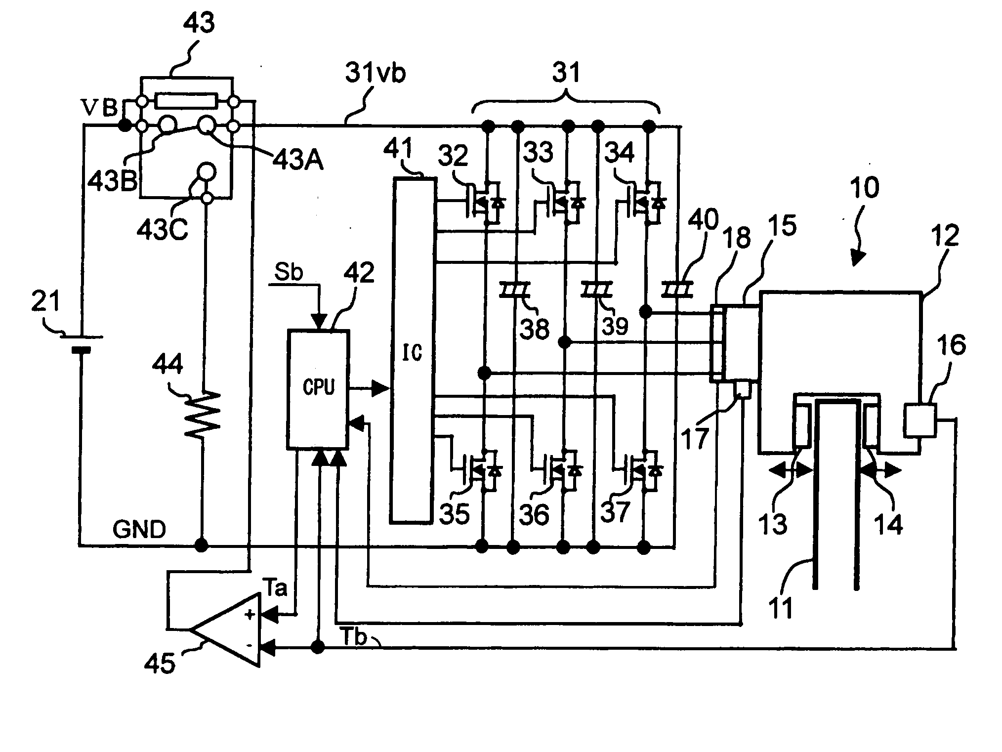
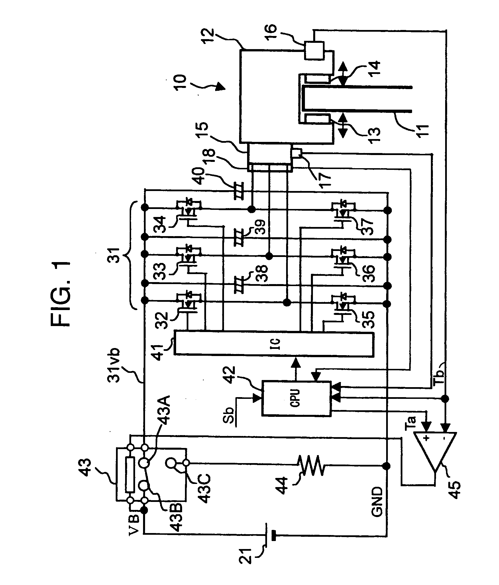
[0025]FIG. 1 shows an electro mechanical brake. The electro mechanical brake 10 is mounted on each vehicle wheel and has a brake disk rotor 11 and an electric power caliper 12.

[0026] The electric power caliper 12 has a pair of brake pads 13 and 14 mounted on both sides of the brake disk rotor 11 and an electric motor 15 as a braking force generator for driving the brake pads 13 and 14. The electric power caliper 12 brakes the wheel by squeezing the brake disk rotor 11 between the brake pads 13 and 14.

[0027] As the electric motor 15, a three-phase electric motor (three-phase a.c. electric motor) is generally used because of the structural advantages in terms of controllability and lifetime.

[0028] The electric power caliper 12 has a built-in structure for converting a rotation motion of the electric motor 15 by coil magnetization into a linear motion. The electric power caliper 12 is a device for linearly moving the brake pads 13 and 14 to squeeze (push) the brake disk rotor 11 and ...

second embodiment

[0052] With reference to FIG. 3, description will be made on the second embodiment in which the control apparatus for the electric motor of the present invention is applied to the control apparatus for an electro mechanical brake. In FIG. 3, components similar to those shown in FIG. 1 are represented by identical reference numerals to those shown in FIG. 1 and the description thereof is omitted.

[0053] In the second embodiment, the arithmetic comparison for generating a command signal to the relay switch 43 is performed by software of the microcomputer 42, i.e., by a program to be executed by the microcomputer 42.

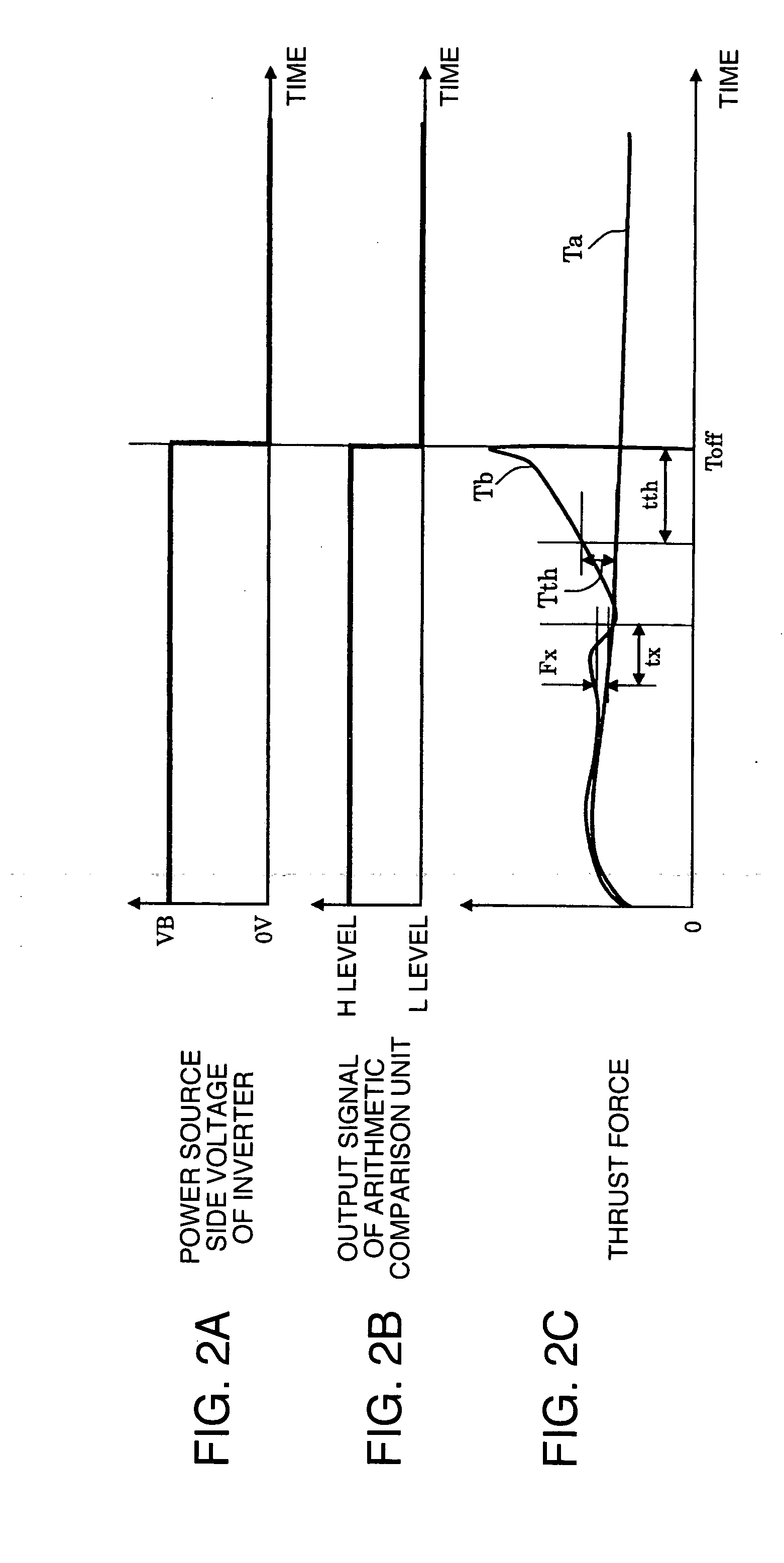
[0054] An arithmetic comparison routine 46 is executed by a real time interrupt. The microcomputer 42 compares the signal representative of the thrust force Tb input from the thrust force sensor 16 with the thrust force command value Ta obtained by the arithmetic process by the microcomputer 42. If a deviation F=the actual thrust force Tb—the thrust force command value Ta i...

third embodiment

[0063] With reference to FIG. 5, description will be made on the third embodiment in which the control apparatus for the electric motor of the present invention is applied to the control apparatus for an electro mechanical brake. Also in FIG. 5, components similar to those shown in FIG. 1 are represented by identical reference numerals to those shown in FIG. 1 and the description thereof is omitted.

[0064] The third embodiment has a second microcomputer 47 in addition to the microcomputer 42 (in this embodiment, hereinafter called a first microcomputer 42). The first and second microcomputers 42 and 47 can communicate with each other.

[0065] Similar to the first embodiment, the first microcomputer 42 has as its inputs: an operation signal corresponding to a depression amount of an unrepresented brake pedal; a signal representative of the actual thrust force Tb output from the thrust force sensor 16; a signal representative of the motor rotation position output from the rotation posit...


PUM


Abstract

A relay switch for selectively connecting a power supply line of an inverter to a ground line is inserted between the inverter and a power source, and a power consumption unit such as a resistor element is inserted between the relay switch and ground line.

Description

BACKGROUND OF THE INVENTION [0001] The present invention relates to a control apparatus for an electric motor and a control apparatus for an electro mechanical brake, and more particularly to a control apparatus for an electric motor of an inverter system and a control apparatus for an electro mechanical brake to be used for a vehicle such as an automobile. [0002] Controlling a torque of an electric motor by an inverter is applied to various electric motor control systems of a vehicle such as an automobile, e.g., an electric power running system, an electric power steering and an electro mechanical brake, respectively of an electric power automobile. [0003] In such electric motor control systems, a power source input to an electric motor is short circuited in an abnormal state such as a turn-off of a main switch (e.g., refer to JP-A-9-47055). [0004] In an electro mechanical brake using an electric motor as a thrust force source, as a fail safe for a defective wheel with a defect in ...

Claims


Application Information

Patent Timeline
Patent Type & Authority Applications(United States)
IPC IPC(8): B60T17/22F16D65/14F16D65/18F16D121/24H02P3/04H02P3/12H02P6/06H02P6/08H02P6/24H02P6/28
CPCH02P3/04
Inventor KURAMOCHI, YUICHIMANAKA, TOSHIO
Owner HITACHI LTD
Why Eureka
Try Eureka