

Auxiliary power source device, fixing device, image forming apparatus and charge operation control method
a technology of auxiliary power source and fixing device, which is applied in the direction of electrographic process, instruments, transportation and packaging, etc., can solve the problems of capacitor cell degradation, difference in charge amount among the respective capacitor units,
- Summary
- Abstract
- Description
- Claims
- Application Information
AI Technical Summary
Benefits of technology
Problems solved by technology
Method used
Image

Examples
first embodiment
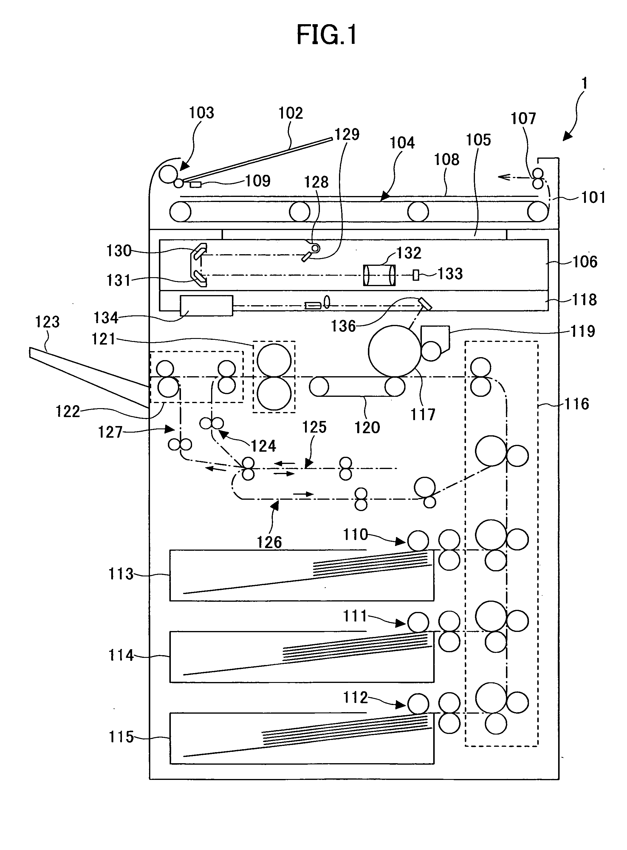
[0034]FIG. 1 is an elevational sectional front view showing a general configuration example of a digital copier 1 according to the present invention. This digital copier 1 acts as an embodiment of an image forming apparatus according to the present invention, and is a so-called composite machine. That is, the digital copier 1 has, in addition of a copy function, a printer function and a facsimile function. By operating an application switching key of an operation part not shown, it is possible to select one from among the copy function, the printer function and the facsimile function in sequence in a switching manner. Thereby, when the copy function is selected, a copy mode is entered; when the printer function is selected, a printer mode is entered; or when the facsimile function is selected, a facsimile mode is entered.
[0035] Next, a general configuration of the digital copier 1 and operation thereof in the copy mode are described. In FIG. 1, in a automatic document feeder (referr...
second embodiment
[0101]FIG. 11 shows a general flow chart of an example of control of charging operations of the capacitor chargers 203a and 203b in the A transition target voltage (for example, 40 V) lower than the final target voltage (for example, 45 V) is previously set. The charging operation is carried out under the control of the CPU 241.
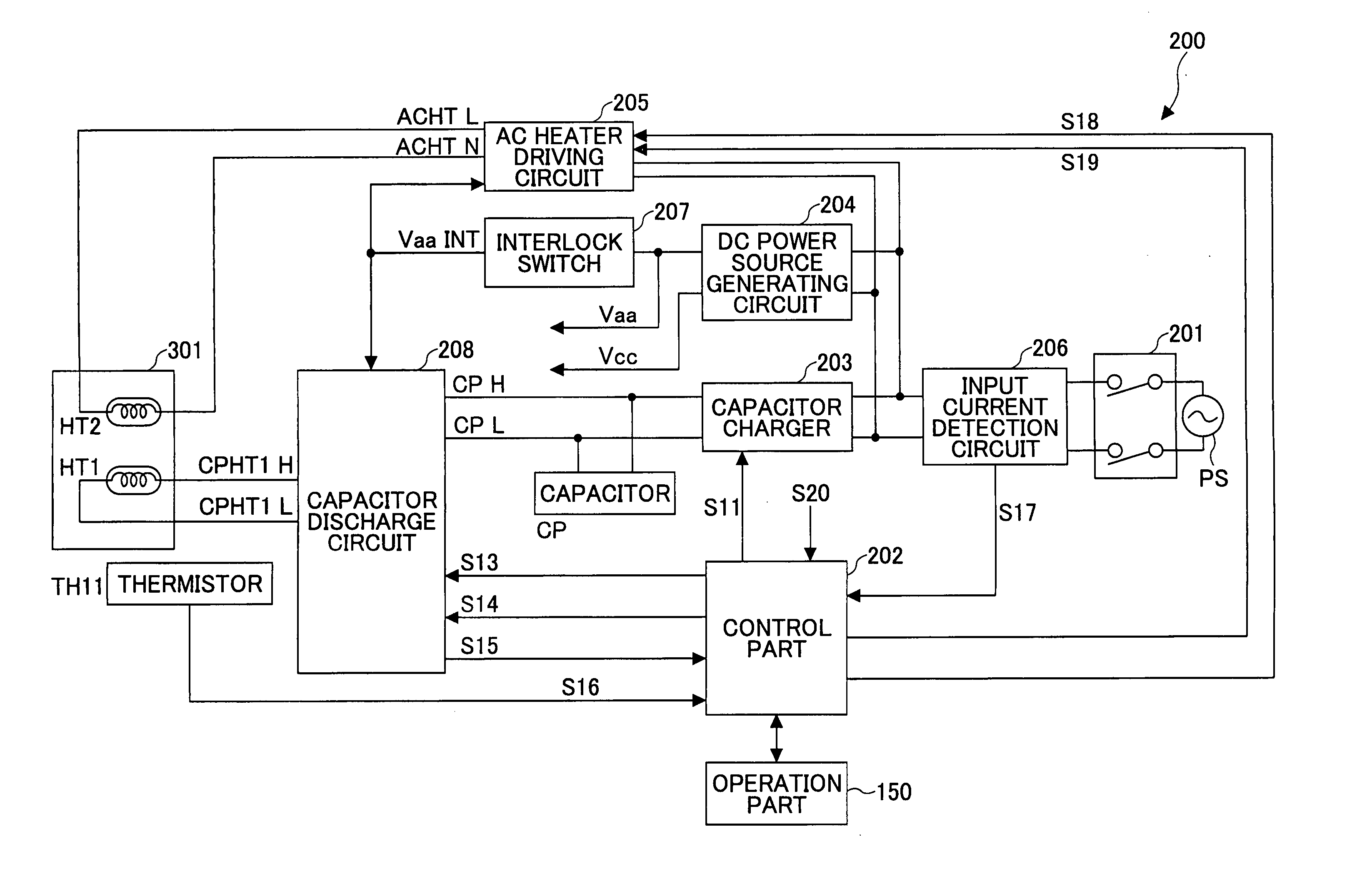
[0102] Basically, the charging operation for the capacitor CP is carried out when the terminal voltage of the entire capacitor CP lowers from a predetermined voltage. The voltage signal S15 from the terminal voltage detection circuit 232 is monitored and thereby, it is determined whether or not the charging is needed (Step S1).
[0103] When it is determined that the charging is needed as a result of the terminal voltage of the capacitor CP lowers from the predetermined voltage, with the use of the voltage signal S15 (Yes in Step S1), the voltage signals S20a and S20b at an initial state of the charge beginning obtained from the terminal voltage detection circ...
third embodiment
[0114] the present invention is described next with reference to FIG. 12. The third embodiment is an embodiment in which the present invention is applied for a case where the digital copier 1 has a so-called energy saving mode.
[0115] The digital copier according to the third embodiment of the present invention has a function for the energy saving mode. That is, in the digital copier 1, when a predetermined requirement is met, that is, when a predetermined time has elapsed while a standby state continues in which the digital copier 1 is not actually used, or such, power is supplied only to a part of a power load, while a power supply is stopped for the remaining almost all the other power loads. Thus, power saving or energy saving is achieved. In this case, when further a predetermined condition (referred to as a recovery condition) is met after the power supply to the almost all the power loads has been stopped, that is, when a user touches an operation key of the operation part (no...
PUM
 Abstract
Description
Claims
Application Information