Controller of vehicle driving device

a technology of driving device and controller, which is applied in the direction of battery/cell propulsion, instruments, etc., can solve the problems of delay in the speed change operation, and achieve the effects of reducing the thermal load of the electric motor, accelerating faster, and improving the response of the speed change operation under the speed change mode to apply a power source braking

Inactive Publication Date: 2009-05-28
TOYOTA JIDOSHA KK
View PDF13 Cites 8 Cited by
  • Summary
  • Abstract
  • Description
  • Claims
  • Application Information

AI Technical Summary

Benefits of technology

[0014]As explained above, according to the invention, the number of gear stages to be set in the mechanically controlled speed change unit is limited to a small number under the second speed change mode where the power source braking is applied. In case of carrying out a speed change to apply a power source breaking under the second speed change mode, the total speed change ratio, i.e., an entire speed change ratio of the drive unit is set by the gear stage of the mechanically controlled speed change unit in which the number of settable gear stages is limited and the speed change ratio of the electrically controlled speed change unit. In this case, the total speed change ratio which cannot be set by the mechanically controlled speed change unit can be set by varying the speed change ratio of the electrically controlled speed change unit. Namely, the speed change operation is carried out by the electrically controlled speed change unit while fixing the gear stage of the mechanically controlled speed change unit. That is, the speed change operation of the electrically controlled speed change unit is carried out preferentially. The speed change operation of the electrically controlled speed change unit is, i.e., a speed change operation to set the speed change ratio thereof to a target value by varying the speed change ratio continuously. This means that the speed change operation of the electrically controlled speed change unit can be executed more quickly in comparison with that of the mechanically controlled speed change unit. As a result, a response of the speed change operation under the speed change mode to apply a power source braking can be improved.
[0015]The speed change operation of the electrically controlled speed change unit is carried out by controlling the electric motor, and the thermal load of the electric motor is changed according to the gear stage of the mechanically controlled speed change unit. For this reason, the gear stage of the mechanically controlled speed change unit where the thermal load of the electric motor falls within an allowable range is selected out of the limited gear stages. As a result, the thermal load of the electric motor can be reduced relatively, and the fuel economy and durability of the electric motor can be improved.
[0016]If the charging capacity is low, in other words, the amount of charge of the electric storage device is little when applying the power source braking, the high speed side gear stage of the mechanically controlled speed change unit is set. Therefore, an amount of the electric power resulting from running of the vehicle is increased so that a charging of the electric storage device is promoted. To the contrary, in case the charging capacity is high, in other words, the amount of charge of the electric storage device is large, the gear stage and the speed change ratio of individual speed change units are set to consume the electric power resulting from running of the vehicle by said another electric motor. Therefore, the power source braking can be applied sufficiently, and a charging performance can be improved.
[0017]According to the invention, moreover, in case the temperature of the mechanically controlled speed change unit is extremely low, the mechanically controlled speed change unit is restricted to shift to the high speed side gear stage. That is, a low speed side gear stage is set in the mechanically controlled speed change unit, and the speed change ratio of the electrically controlled speed change unit is varied to obtain a target total speed change ratio. For this reason, relative revolution speeds of the rotary elements constituting the mechanically controlled speed change unit, or an absolute revolution speed of the mechanically controlled speed change unit is / are increased. Consequently, an oil temperature is raised promptly. Also, a shifting operation to set the low speed side gear stage may be achieved by activating only one frictional engagement device such as a one-way clutch. In this case, the hydraulic control is relatively less affected by viscosity of the oil so that deterioration in shocks can be prevented or minimized.

Problems solved by technology

For this purpose, an intricate hydraulic control has to be carried out and this causes a delay in the speed change operation.
Especially, in case of carrying out a downshifting by a manual operation, such delay in the speed change may bring discomfort.

Method used


Image

  • Controller of vehicle driving device
  • Controller of vehicle driving device
  • Controller of vehicle driving device

Examples


Embodiment Construction

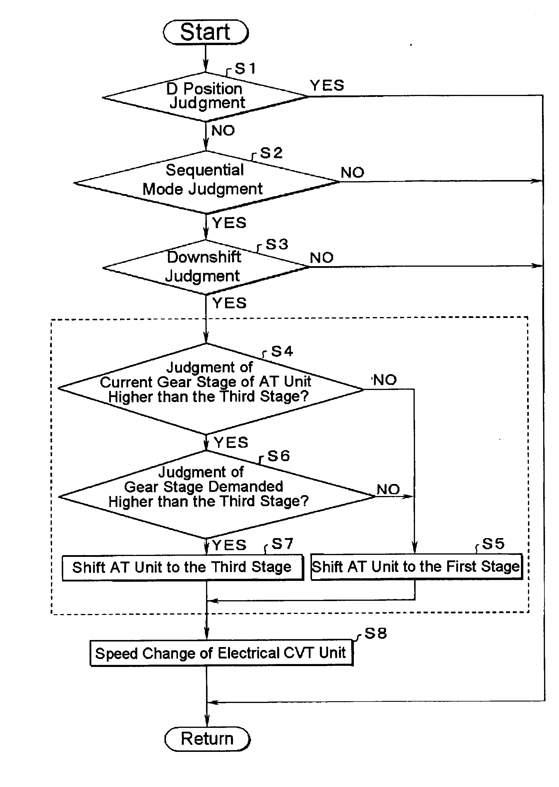
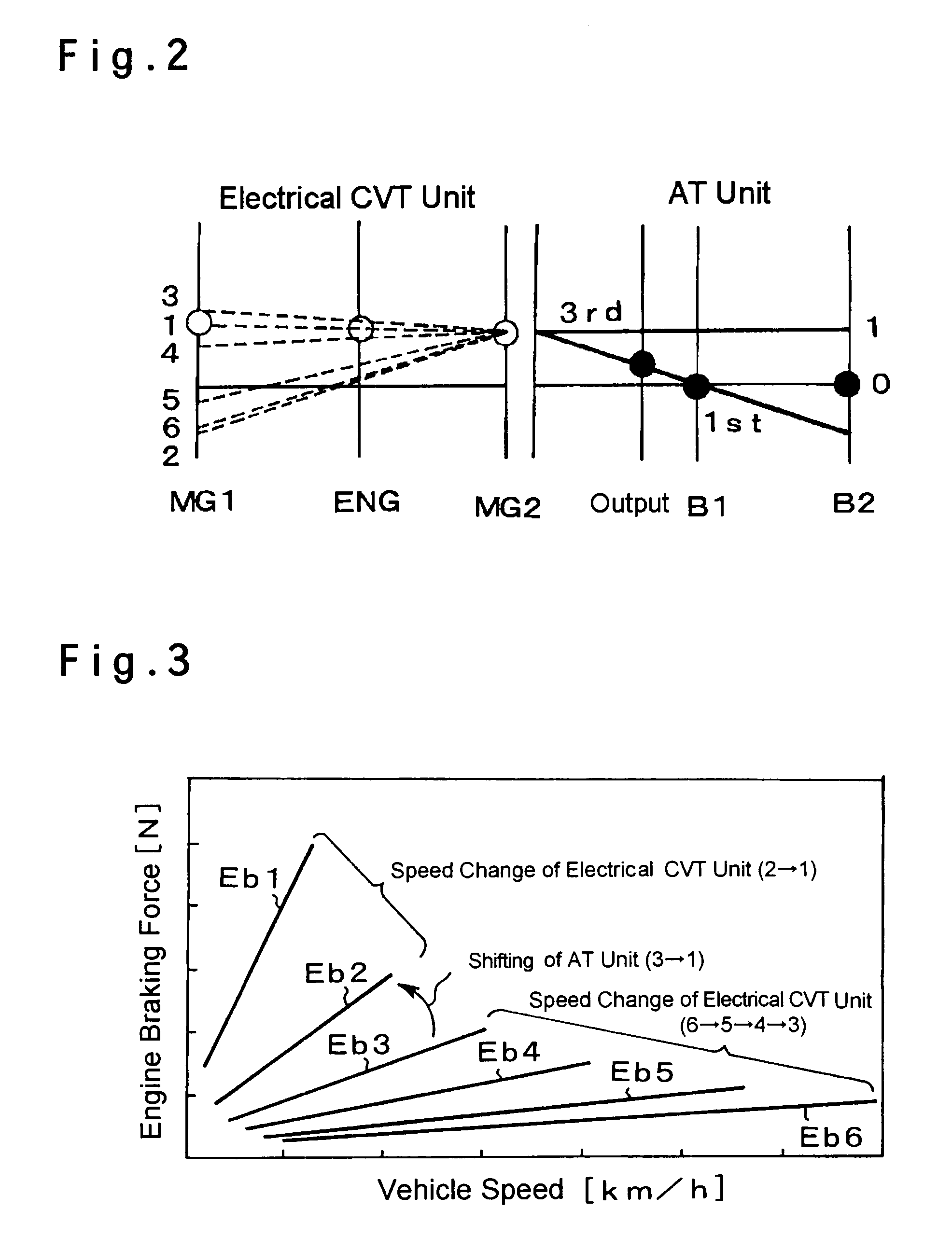
[0029]Next, here will be described the present invention in connection with its specific examples. First of all, one example of a drive unit of a vehicle to which a control system of the invention is applied will be explained hereinafter. FIG. 7 shows an example of the control system arranged in an FR (i.e., Front-engine Rear-drive) type hybrid vehicle Ve (as will be called the “vehicle” hereinafter). The drive unit illustrated in FIG. 7 comprises two kinds of prime movers having different principles of power generation. In this example, an engine 1 and a motor generator 2 (MG2) are employed as prime movers, and a power train and a power transmission route are arranged to transmit both powers outputted from the engine 1 and the motor generator 2 commonly to a (rear) wheel 3. The engine 1 functioning as a prime mover of the vehicle Ve is a power unit converting a thermal energy into a kinetic energy by burning a fuel. Both an internal combustion engine and an external combustion engi...


PUM


Abstract

To execute a manual speed change to apply an engine brake in good response, and to ensure sufficient braking force in a drive unit having a continuously variable speed change unit and a geared speed change unit.
For this purpose, a control system for a drive unit of a vehicle, in which a speed change mode can be selected from a first speed change mode wherein a total speed change ratio governed by the speed change ratio of the continuously variable speed change unit and the gear stage of the geared speed change unit is set on the basis of a running condition of a vehicle, and a second speed change mode wherein the total speed change ratio is set on the basis of a signal for applying a power source braking comprises: a gear stage limiting means for reducing number of gear stages of the geared speed change unit settable under the second speed change mode smaller than that under the first speed change mode; and wherein the total speed change ratio is set according to the gear stage of the geared speed change unit set by the gear stage limiting means, and to the speed change ratio of the continuously variable speed change unit, in case the second speed change mode is selected.

Description

TECHNICAL FIELD[0001]This invention relates to a drive unit of a vehicle having an electrically controlled speed change unit and a mechanically controlled speed change unit, and more particularly, to a system for controlling a speed change ratio of the vehicle.BACKGROUND ART[0002]This kind of drive unit of a vehicle of is disclosed in Japanese Patent Laid-Open No. 2003-127681. Objectives of the invention disclosed in Japanese Patent Laid-Open No. 2003-127681 is to suppress an increase in size of an electric motor, and to obtain driving force in accordance with a various vehicle speeds. In the hybrid-vehicle drive system taught by Japanese Patent Laid-Open No. 2003-127681, an internal combustion engine is connected with a carrier of a planetary gear mechanism, a first electric motor / generator is connected with a sun gear of the planetary gear mechanism, and a member of an input side of a transmission is connected with a ring gear. The transmission is a geared transmission such as an ...

Claims


Application Information

Patent Timeline
Patent Type & Authority Applications(United States)
IPC IPC(8): F16H61/21B60K6/445B60K6/543B60K6/547B60L50/16B60W10/10B60W10/26B60W20/00F16H59/42F16H59/70F16H61/02F16H61/68F16H61/684F16H61/686
CPCB60K6/365Y10T477/23B60K6/543B60K6/547B60W10/08B60W10/11B60W20/00B60W30/18109F16H61/21F16H61/66254F16H61/70B60L11/123B60L11/14Y02T10/6239Y02T10/7077Y02T10/6217Y10T477/653B60K6/445B60L50/61B60L50/16Y02T10/62Y02T10/7072Y02T10/70B60W10/18B60W20/30B60W10/101
Inventor SHIBATA, HIROYUKIMATSUBARA, TOORUOHTA, TAKASHIKOMADA, HIDEAKIIDESHIO, YUKIHIKO
Owner TOYOTA JIDOSHA KK
Why Eureka
Try Eureka