Laser unit, exposure apparatus and method

a laser unit and exposure apparatus technology, applied in the field of laser units, can solve the problems of inability to meet the demand for high-quality exposure, the permissible variable width of the exposure apparatus gradually reduces, and the prior art cannot control the fluctuation of the spectral bandwidth, so as to achieve stable spectral bandwidth and high-quality exposure

Inactive Publication Date: 2005-09-01
CANON KK
View PDF15 Cites 14 Cited by
  • Summary
  • Abstract
  • Description
  • Claims
  • Application Information

AI Technical Summary

Benefits of technology

[0006] Accordingly, it is an exemplary object of the present invention to provide a laser unit, and an exposure method and apparatus using the same, and a device manufacturing method, for the stable spectral bandwidth and the high-quality exposure.

Problems solved by technology

However, prior art does not control the fluctuation of the spectral bandwidth, and ignores the influence.
However, as the CD becomes smaller with the higher resolution, the permissible variable width for the exposure apparatus gradually reduces and is no longer a negligible factor.
Even when the spectral bandwidth is within an optimization range, when the variance exceeds the permissible range of the exposure apparatus, for example, when the CD for the line and space (“L&S”) pattern is different from the CD for the isolated pattern, the demand for the high-quality exposure cannot be met.

Method used


Image

  • Laser unit, exposure apparatus and method
  • Laser unit, exposure apparatus and method
  • Laser unit, exposure apparatus and method

Examples


Embodiment Construction

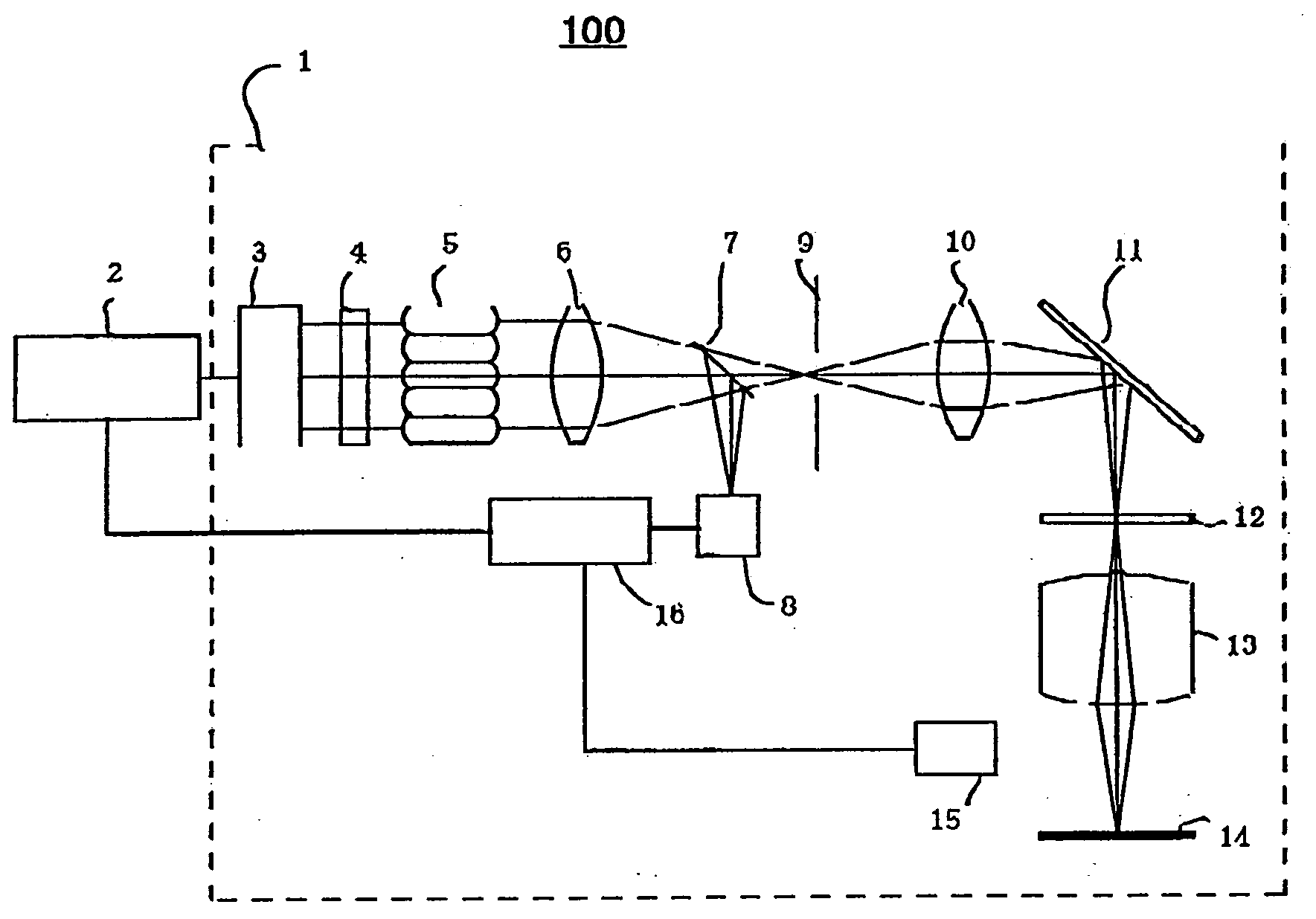
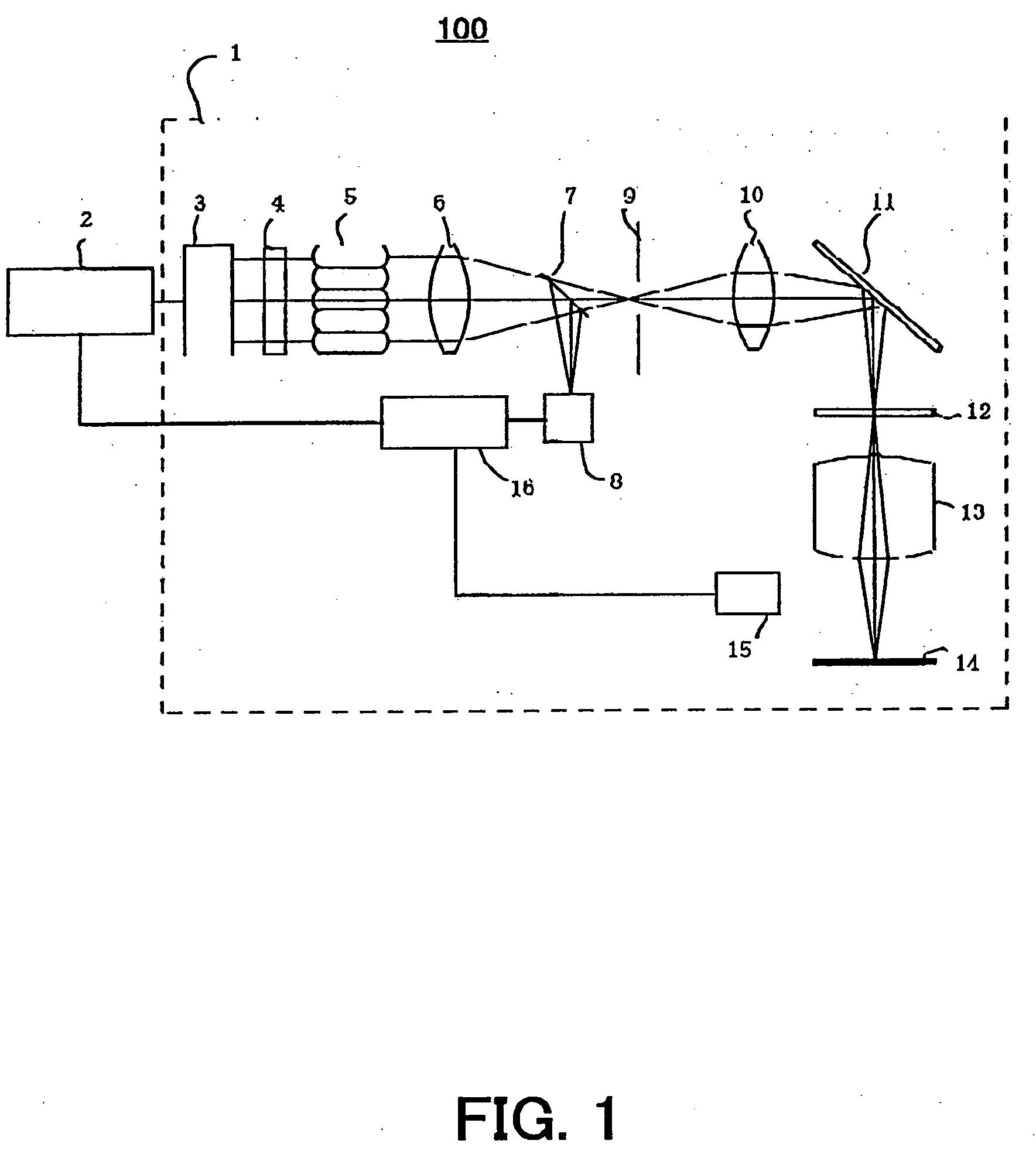
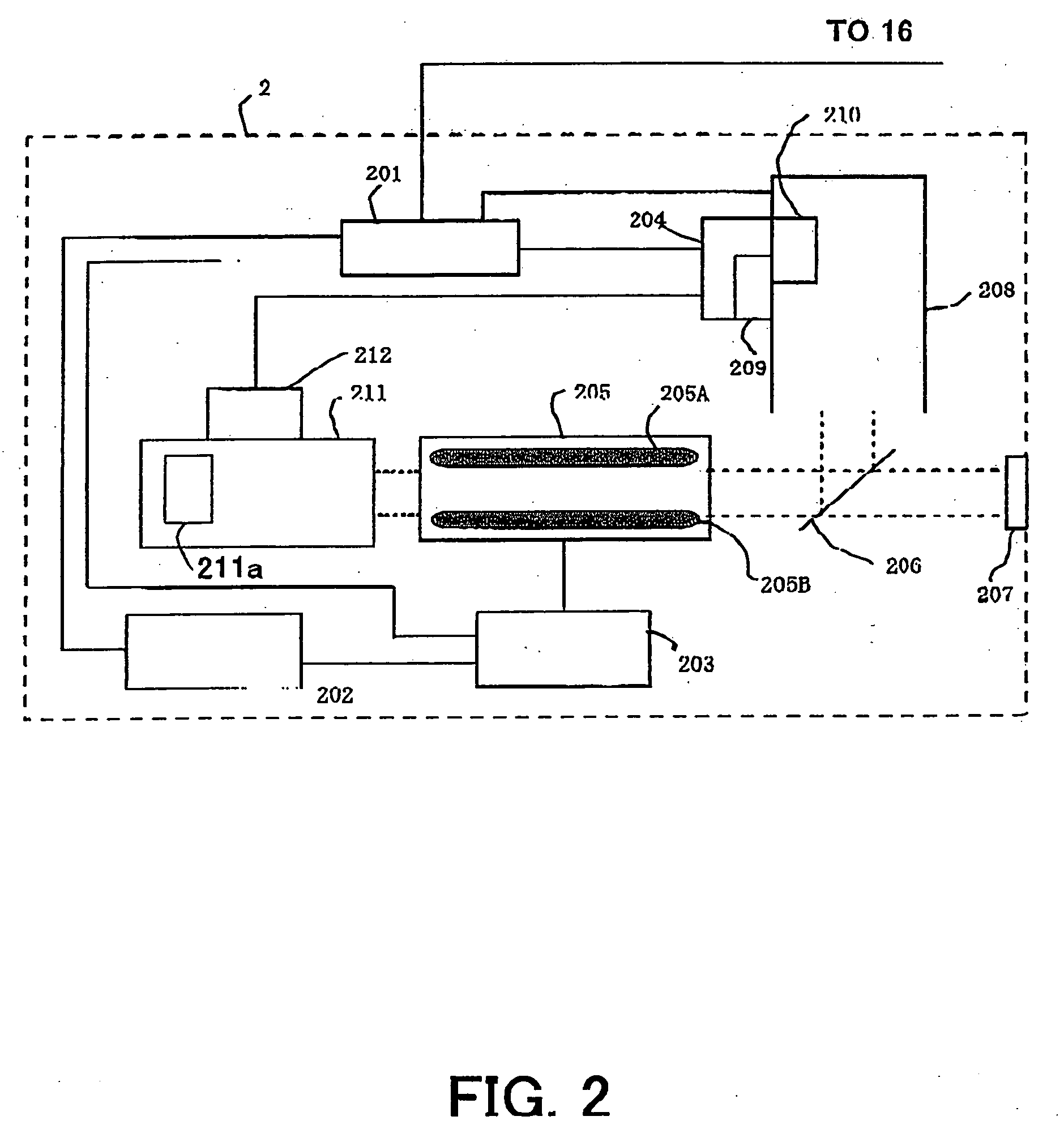
[0026] Referring now to the accompanying drawings, a description will be given of an exposure apparatus 100 according to tho present invention. 1 denotes an exposure apparatus body of a stepper or a step-and-repeat type. Alternatively, the exposure apparatus body 1 may be a scanner or a step-and-scan type. 2 denotes a laser light source that uses an inert gas halide excimer laser (or a so-called excimer laser) as one example of the laser unit, such as a KrF excimer laser (with a wavelength of 248 nm) and an ArF excimer laser (with a wavelength of 193 nm).

[0027] The exposure apparatus body 1 includes, along an optical path of the laser beam from the laser unit 2, a beam shaping optical system 3 that shapes a section of a laser beam from the light source 2 into a desired shape, a variable ND filter 4 that adjusts the light intensity of the laser beam, an optical integrator 5 that splits the laser beam and overlaps the split laser beams in order to make the uniform intensity on a reti...


PUM

PropertyMeasurementUnit
wavelengthaaaaaaaaaa

Abstract

A laser unit for oscillating a laser of a first wavelength spectrum includes a wavelength selector for determining a first wavelength spectrum, and a drive mechanism for changing the first wavelength spectrum at a predetermined period.

Description

BACKGROUND OF THE INVENTION [0001] The present invention relates generally to a laser unit, an exposure apparatus and method using the same as a light source, and a device manufacturing method. [0002] A projection optical system has conventionally been used to transfer a pattern on a mask (or a reticle) onto a wafer etc. via a projection optical system. Along with recent demands for the finer processing to the semiconductor device, the high-resolution and high-quality exposure have increasingly demanded. As one means for implementing the high resolution, use of the exposure light having a shorter wavelength is promoted: An exposure light source is transited from the KrF laser (with a wavelength of about 248 nm) to the ArF laser (with a wavelength of about 193 nm), and the practical implementation of the F2 laser (with a wavelength of about 157 mm) is now reviewed. [0003] The laser has a spread or a spectrum around a predetermined wavelength, and the excessively wide spectrum causes ...

Claims


Application Information

Patent Timeline
Patent Type & Authority Applications(United States)
IPC IPC(8): G03F7/20H01L21/027H01S3/00H01S3/10H01S3/106H01S3/13H01S3/137
CPCH01S3/106G03F7/70575
Inventor SUKEGAWA, TAKASHITAKAHASHI, KAZUHIRO
Owner CANON KK
Why Eureka
Try Eureka