
Automatic delays for alignment of signals

a technology of automatic delay and alignment, applied in the field of signal generation, can solve the problems of inconvenience for users, difficulty in aligning digital marker signals with data signals in practice, and analog signals may be delayed in time with respect to the output of digital markers, so as to reduce relative delays

Active Publication Date: 2005-09-01
NATIONAL INSTRUMENTS
View PDF26 Cites 12 Cited by
  • Summary
  • Abstract
  • Description
  • Claims
  • Application Information

AI Technical Summary

Benefits of technology

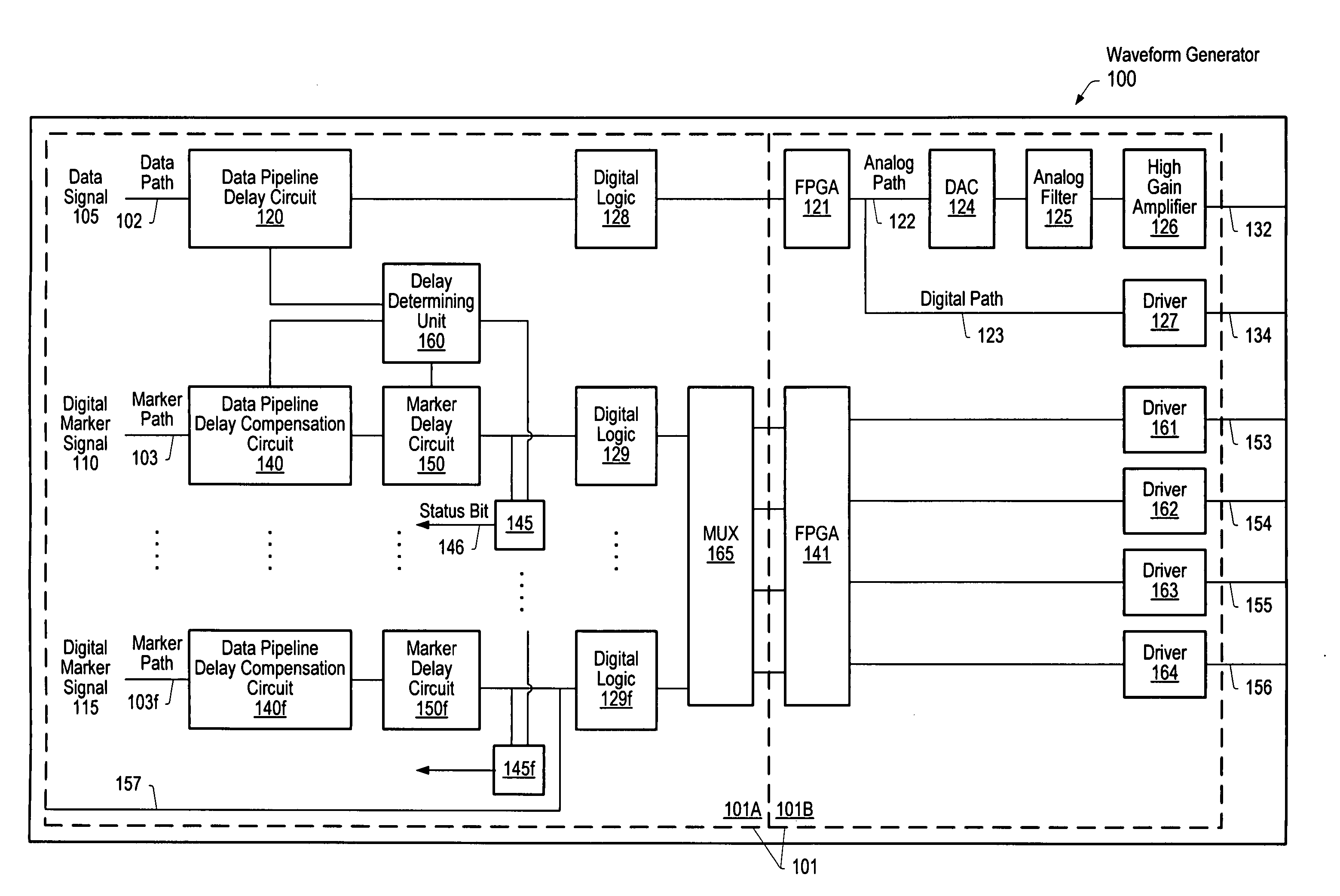
The patent describes a system and method for delaying the output of two signals from different sources. The system can automatically determine the delay between the two signals and program a delay circuit to delay the output of the first signal to align with the second signal. Users can also program the delay circuit to add additional delays or reduce the determined delay. The technical effect of this patent is to provide a reliable and efficient way to align the output of two signals in a waveform generator.

Problems solved by technology

Therefore, the output of the analog signal may be delayed in time with respect to the output of the digital markers, since the DAC and the other components in the travel path associated with the analog signal delay the output of the analog signal.
The alignment of digital marker signals with data signals is difficult in practice.
However, this may be an inconvenience to the user and may still lead to unexpected, inaccurate results.
For example, even if the user were able to empirically deal with an alignment problem for a particular group of settings, the user may face a different mismatch when the settings are changed, for example, by turning on an analog filter or changing an interpolation rate.
In the past, when sampling rates were much lower, the delays between the output of digital markers and data signals were often tolerable.
However, with current sample rates, the delays may pose a significant problem, and as sampling rates increase, for example, from 100 MHz (10 ns per sample) to 200 MHz (5 ns per sample) and higher, the delay issue will become even more important.
The same issues described above with regard to aligning digital marker signals with waveform signals also apply to the more general case of aligning waveforms or other signals from multiple sources.

Method used


Image

  • Automatic delays for alignment of signals
  • Automatic delays for alignment of signals
  • Automatic delays for alignment of signals

Examples


Embodiment Construction

Aligning Signals from Multiple Sources

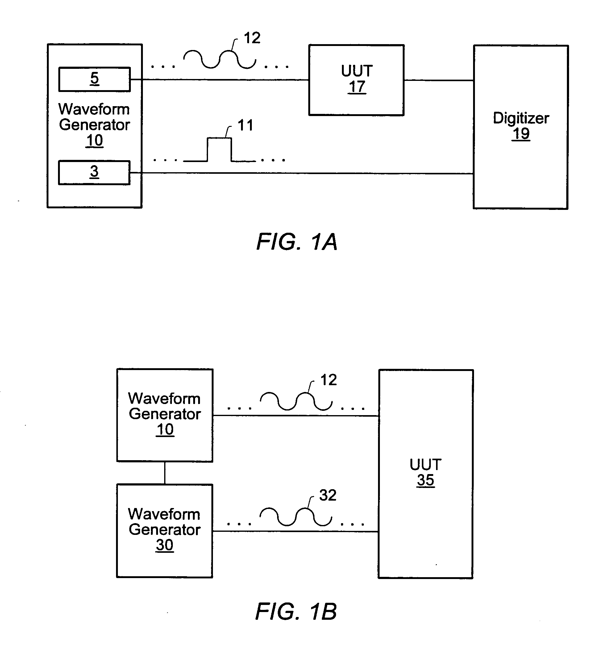
[0040]FIG. 1A illustrates a block diagram of one embodiment of a waveform generator 10 for generating a plurality of signals. In one embodiment, waveform generator 10 may be a standalone waveform generator or a computer-based waveform generator. Furthermore, waveform generator 10 may be an arbitrary waveform generator or digital waveform generator (i.e., logic signal source). In one embodiment, waveform generator 10 may be configured to align signals from multiple sources.

[0041] In one embodiment, waveform generator 10 may be operable to delay output of a first signal 11 provided by a first source 3 with respect to output of a second signal 12 provided by a second source 5. In one embodiment, waveform generator 10 may comprise a delay determining unit that may be operable to determine a relative delay between the first signal 11 and the second signal 12, based upon a travel path via source 3 of the first signal 11 and a travel path via source...


PUM


Abstract

In one embodiment, a system comprises a delay determining unit that may be operable to determine a relative delay between the first signal provided by the first source and the second signal provided by the second source, based upon a travel path of the first signal and a travel path of the second signal. In addition, a delay circuit, comprised within the waveform generator, may be configured to be programmed to delay output of the first signal to output the first signal at a predetermined position with respect to output of the second signal, based on the determined relative delay. More specifically, in one embodiment, the delay circuit may be configured to be automatically programmed to add the relative delay to the output of the first signal to automatically align the output of the first signal with respect to the output of the second signal.

Description

PRIORITY CLAIM [0001] This application claims benefit of priority of U.S. provisional application Ser. No. 60 / 548,290 titled “Automatic Delays for the Alignment of Data and Digital Markers”, filed Feb. 27, 2004, and whose inventors are Neil S. Feiereisel and Craig M. Conway.BACKGROUND OF THE INVENTION [0002] 1. Field of the Invention [0003] This invention relates to signal generation and, more particularly, to signal generation with automatic delays for alignment of signals from multiple sources. [0004] 2. Description of the Related Art [0005] Signal generation is used in a wide variety of applications, including, for example, industrial testing and verification, product design, and control, among others. In one application of signal generation, a signal is generated according to waveform data, and provided as input or stimulus to a unit under test (UUT). Resulting output from the UUT may then be analyzed to characterize the UUT, e.g., for quality control, design feedback, etc. Gene...

Claims


Application Information

Patent Timeline
Patent Type & Authority Applications(United States)
IPC IPC(8): H04J3/06H04L7/00H04L25/14
CPCH04L25/14H04J3/0682
Inventor FEIEREISEL, NEIL S.CONWAY, CRAIG M.
Owner NATIONAL INSTRUMENTS
Learn More