Image forming apparatus and its control method

a technology of forming apparatus and fusing device, which is applied in the direction of electrographic process apparatus, instruments, optics, etc., can solve the problems of increasing the driving torque of the fusing device, increasing the cost of the device, and insufficient heat supplied to the toner on the printing material, so as to prevent the deformation of the printing material and stable fusing performance

Inactive Publication Date: 2005-09-01
CANON KK
View PDF15 Cites 14 Cited by
  • Summary
  • Abstract
  • Description
  • Claims
  • Application Information

AI Technical Summary

Benefits of technology

[0026] It is an object of the present invention to provide an image forming apparatus and its control method which can prevent deformation of a printing material and obtain stable fusing performance by automatically switching optimal fusing conditions in accordance with the type of printing material and the state of a fusing device.

Problems solved by technology

This is because the contact area between the heating member and the printing material decreases in the fusing nip area, and a sufficient amount of heat is not supplied to the toner on the printing material.
The method of increasing the fusing pressurizing force, however, leads to an increase in the driving torque of the fusing device and hence tends to increase the device cost.
This makes it difficult to increase the pressurizing force; the total pressure is limited to about 196 N (20 kgf) at most, and the linear pressure in the fusing nip area is set to be relatively low.
If, however, the fusing temperature is simply raised, an excessive amount of heat is supplied to a thin sheet or a sheet with good surface properties.
This may lead to adverse effects, e.g., the occurrence of hot offset and an increase in the amount of curl of a sheet.
For this reason, if fusing temperature setting is made in consideration of variations in fusing nip width, it is very difficult to satisfy requirements for all the phenomena such as fusing properties, curl, and hot offset with respect to various types of printing materials described above by setting only one temperature.
As described above, it is difficult to set fusing conditions optimal for both a printing material with rough surface properties and a printing material with good smoothness.
It is, however, difficult for the user to set a fusing mode in accordance with a parameter like surface roughness that is incomprehensible to the user.
The following problems, however, have arisen in the conventional thermal fixing device described above.
This makes it impossible to accurately detect the temperature of the printing material.
The heat capacity of the roller as the facing member cannot be neglected, and hence it is difficult to make a noticeable difference in the temperature detection thermistor in accordance with the surface roughness or thickness of a printing material.
This makes it difficult to accurately discriminate the type of printing material in every case.
If, however, the temperature detection element is actually placed next to the fusing nip, the influence of ambient temperature cannot be neglected.
This makes it difficult to accurately discriminate the type of printing material and optimally control the thermal fixing device.
As a consequence, the sensor cannot correctly detect the temperature of the printing material.
On the other hand, temperature detection is most susceptible to the influence of steam from the printing material immediately after it is delivered from the fusing nip.
In this case, however, this air path influences the temperature of the surface of a printing material.
In consideration of variations in wind velocity, it is difficult to discriminate the printing material.
As described above, in practice, no technique has been developed to discriminate the type of printing material by measuring the temperature of the printing material using a non-contact type sensor such as an infrared sensor.

Method used


Image

  • Image forming apparatus and its control method
  • Image forming apparatus and its control method
  • Image forming apparatus and its control method

Examples


first embodiment

(Schematic Arrangement of Image Forming Apparatus)

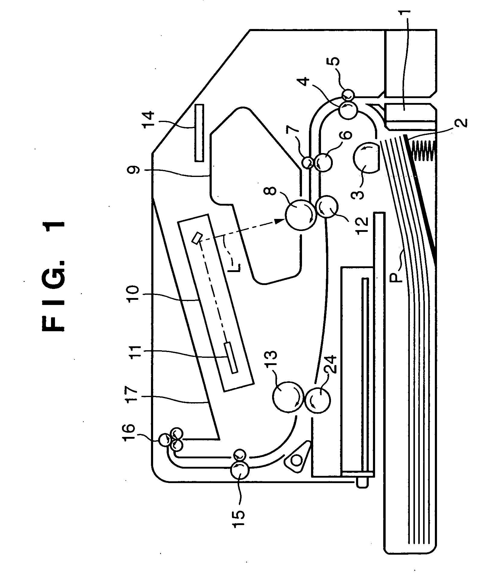
[0054]FIG. 1 is a schematic sectional view of an image forming apparatus according to this embodiment. This image forming apparatus includes a paper feed device comprising a paper feed tray 1, sheet stacking plate 2, and feed roller 3. Printing materials P stacked on the sheet stacking plate 2 in the paper feed tray 1 are picked up one by one by the feed roller 3, starting from the uppermost printing material, and conveyed to a registration unit by convey rollers 4 and 5. After the conveying direction of the printing material P is adjusted by the registration unit comprised of registration rollers 6 and 7, the printing material P is fed to an image forming unit.

[0055] The image forming unit is comprised of a photoconductive drum 8, toner cartridge 9, laser scanner unit 10, transfer drum 12, and the like. Although the illustration of the arrangement of the toner cartridge 9 will be omitted, the toner cartridge 9 has an arrangement ...

second embodiment

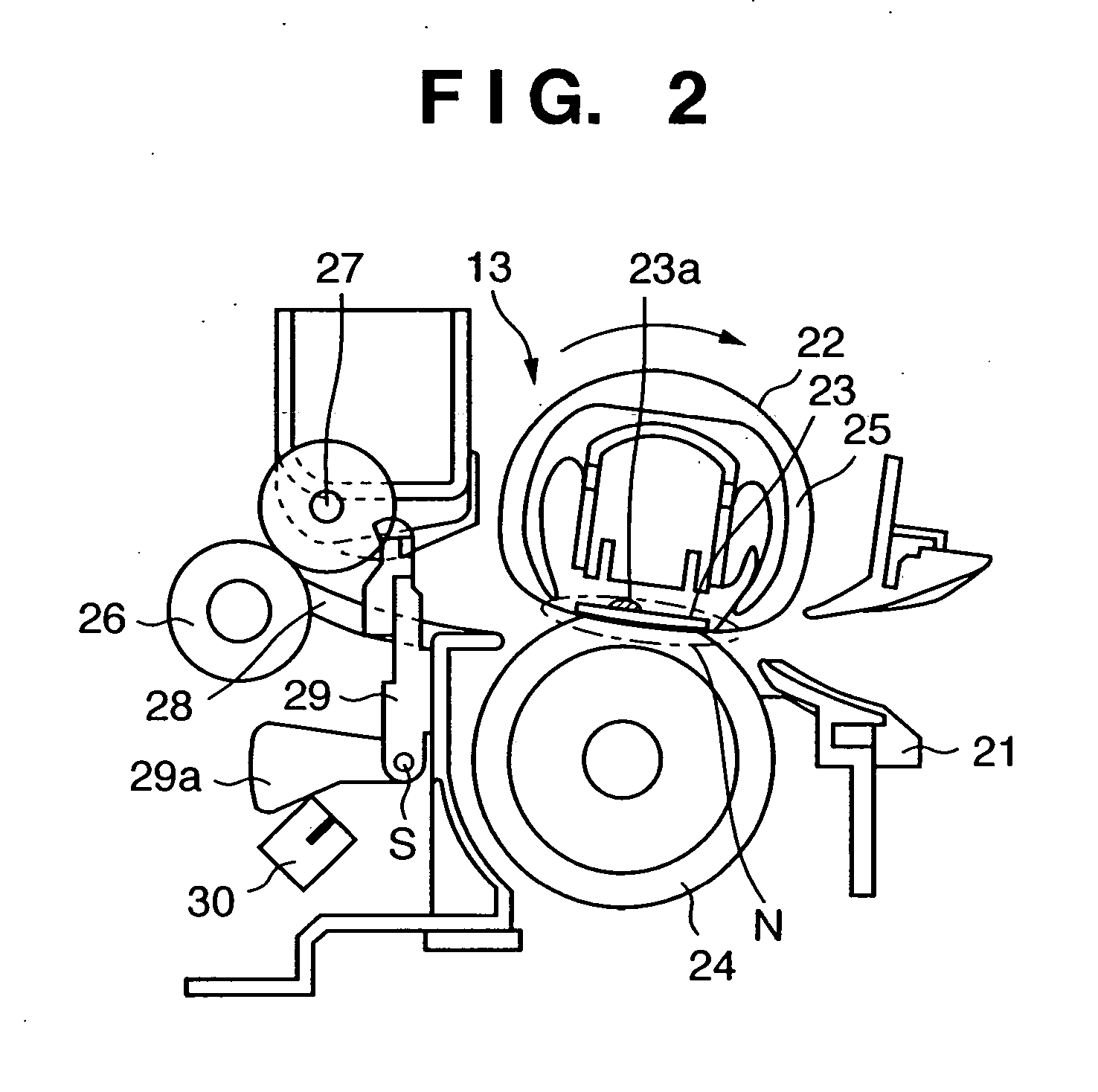
[0112]FIG. 15 shows the arrangement of an image forming apparatus according to the second embodiment. The same reference numerals as in FIG. 1 denote the same constituent elements in FIG. 15, and hence a description thereof will be omitted. In addition, since the arrangement of a thermal fixing device in this embodiment is the same as that in the first embodiment, the thermal fixing device will be described by referring to FIGS. 2 to 8.

[0113] In this embodiment, an outside air temperature sensor 19 such as a thermistor for detecting an environment (room temperature) in which an image forming apparatus is installed is placed on, for example, a side surface of the apparatus body. The outside air temperature sensor 19 is placed near a cooling fan 18, which prevents a rise in temperature inside the apparatus by taking outside air in the apparatus, so as to accurately detect a temperature outside the apparatus. This makes it possible for the outside air temperature sensor 19 to accurate...


PUM


Abstract

In continuous printing operation which repeatedly sets a state in which when a preceding printing material passes through the nip area of a thermal fixing unit, a succeeding printing material has been supplied to an image forming unit and image forming operation has been started, a first temperature indicating an ambient temperature near the thermal fixing unit is measured at an early time point in the continuous printing operation. A second temperature indicating the temperature of the printing material which has passed through the press contact nip portion at a predetermined period of time during the continuous printing operation is measured. The amount of heat to be supplied to the succeeding printing material is controlled on the basis of the measured first and second temperatures.

Description

FIELD OF THE INVENTION [0001] The present invention relates to an image forming apparatus and its control method and, more particularly, an image forming apparatus having a thermal fixing unit that fixes a toner image formed on a printing material by heating it and a control method for the apparatus. BACKGROUND OF THE INVENTION [0002] Many copying machines, printers, and the like based on an electrophotographic method use, as thermal fixing methods, a heating roller fusing method of a contact heating type which exhibits high thermal efficiency and safety and a film heating method of an energy saving type. [0003] As shown in FIG. 19, a thermal fixing device based on the heating roller fusing method is basically comprised of a heating roller (fixing roller) 40 serving as a heating rotating member containing a heater 41 such as a halogen heater and an elastic pressurizing roller 50 serving as a pressurizing rotating member which comes into contact with the heating roller 40 to pressuri...

Claims


Application Information

Patent Timeline
Patent Type & Authority Applications(United States)
IPC IPC(8): G03G15/00G03G21/14G03G15/20
CPCG03G15/2046
Inventor IZAWA, SATORUNIHONYANAGI, KOJIKUBOCHI, YUTAKAINUI, FUMIKIHASHIGUCHI, SHINJI
Owner CANON KK
Why Eureka
Try Eureka