
Scanner with array anti-degradation features

a scanning array and anti-degradation technology, applied in the field of arrays, can solve problems such as signal loss

Active Publication Date: 2005-09-01
AGILENT TECH INC
View PDF18 Cites 12 Cited by
  • Summary
  • Abstract
  • Description
  • Claims
  • Application Information

AI Technical Summary

Benefits of technology

[0014] Whether used in combination with one or more of the above-referenced techniques or alone, the present invention offers a number of superb options in dealing with ozone contamination in the context of array reading or scanning. When the present invention is used in isolation, it offers a solution in a system without any of the above-referenced drawbacks. But when used in combination with the other approaches, the additional benefits the other solutions offer may be worth-while.
[0018] The present invention also offers potential advantages is providing for more reproducibility to re-scan or re-read the same array multiple times. The invention can also reduce experimental variability due to variation in times that different arrays spend in a scanner carousel (or other multiple-array holder) prior to being scanned, for example to different scan slide positions in a slide queue, or simply different scan types used by the operator, or just variations due to a non-repeatable schedule. Accordingly, a reader employing the teachings of the present invention can produce useful read or scan results in situations where at least some of the plurality of arrays loaded into the device are of the same layout, but may have been exposed to different samples. Even if separated by a large number of slides (resulting in an otherwise-signification delay in reading the slides when ozone or other atmospheric contaminant degradation would) in the reader queue, the results will have significantly decreased variability in obtained signals as a result of variation in exposure time to ozone or other atmospheric contaminants.

Problems solved by technology

It is applicable to other chemicals / gasses that might degrade array or dye quality resulting in signal loss due to time spent in a scanner or other type of reader.

Method used


Image

  • Scanner with array anti-degradation features
  • Scanner with array anti-degradation features
  • Scanner with array anti-degradation features

Examples


Embodiment Construction

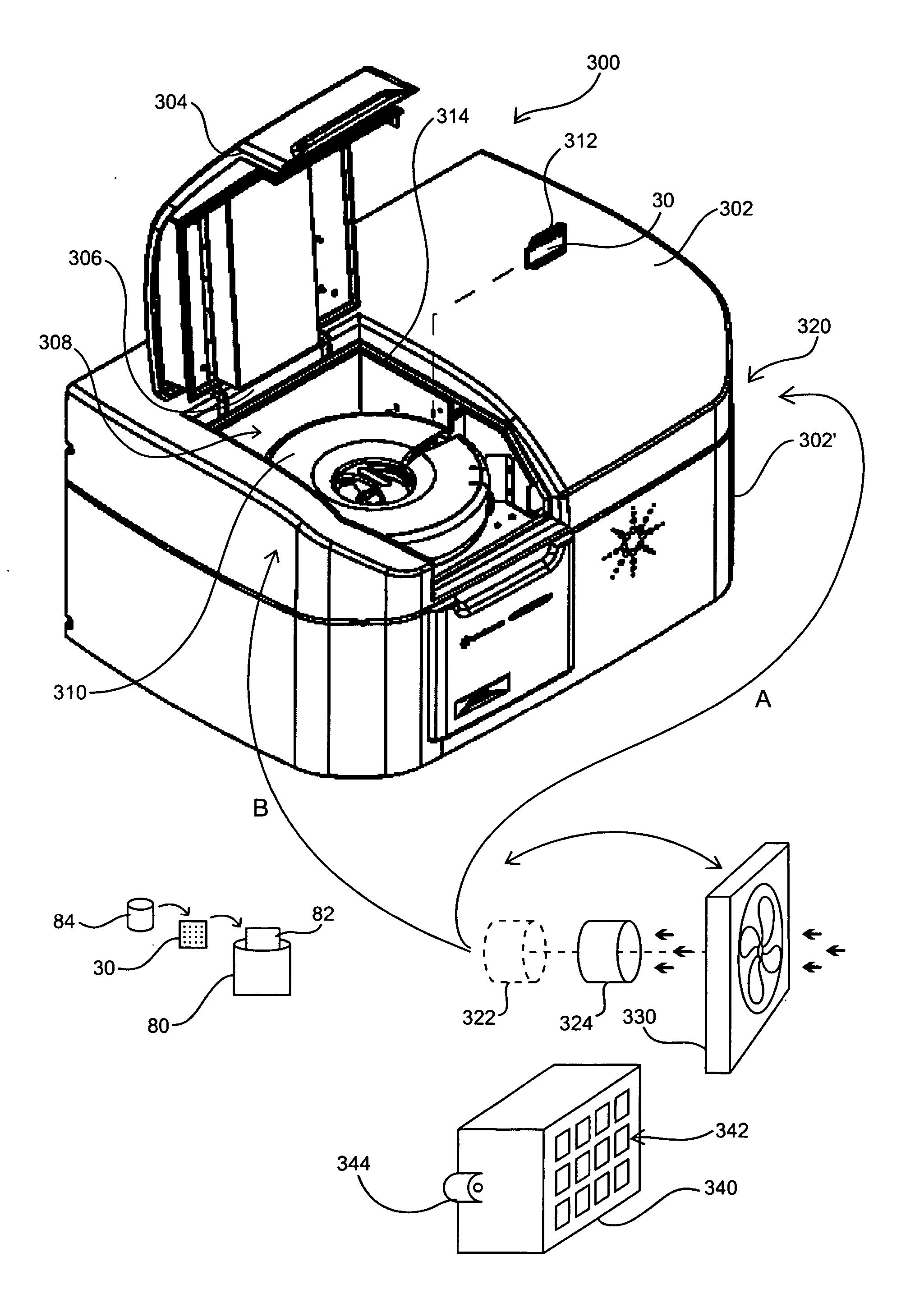
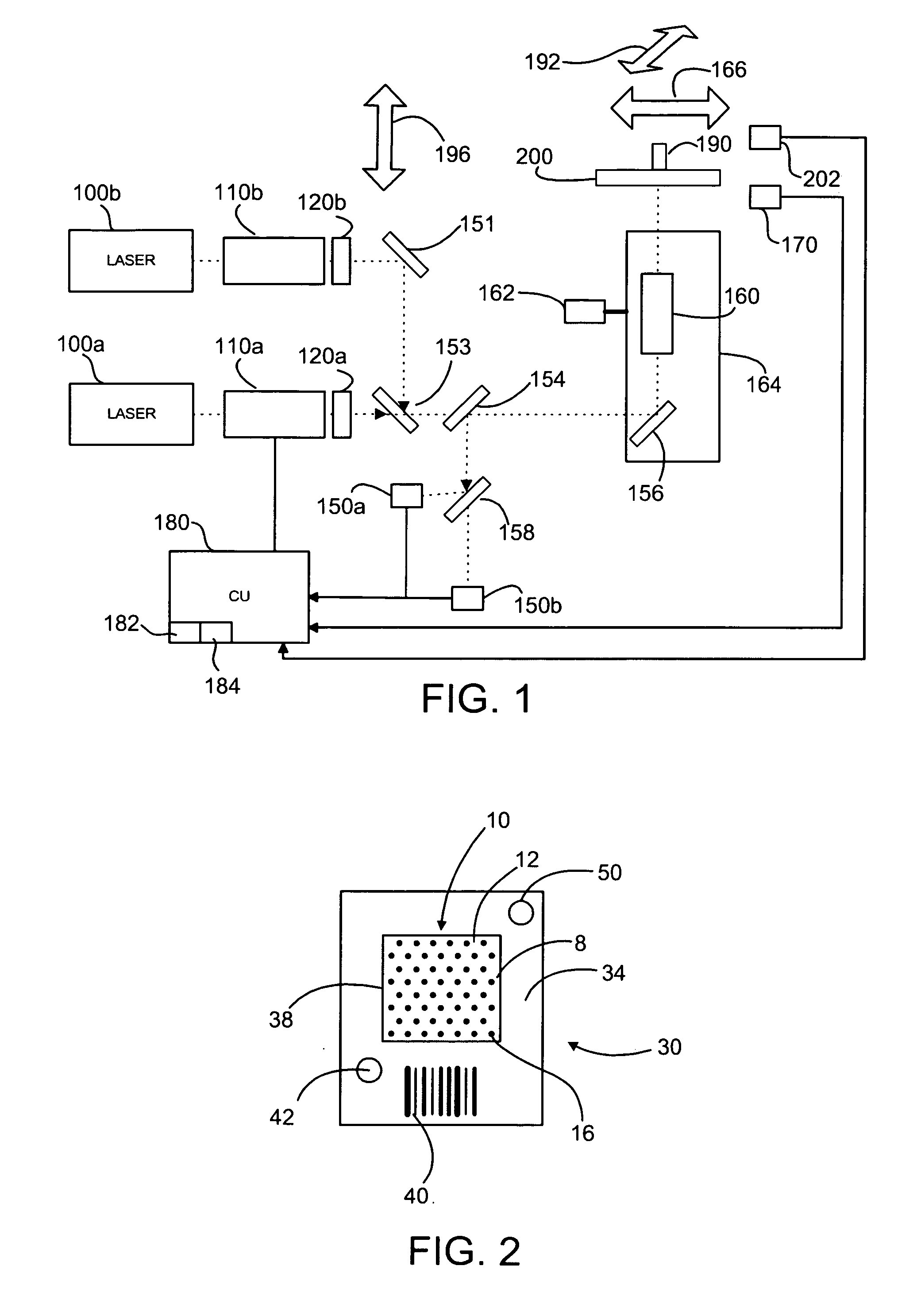
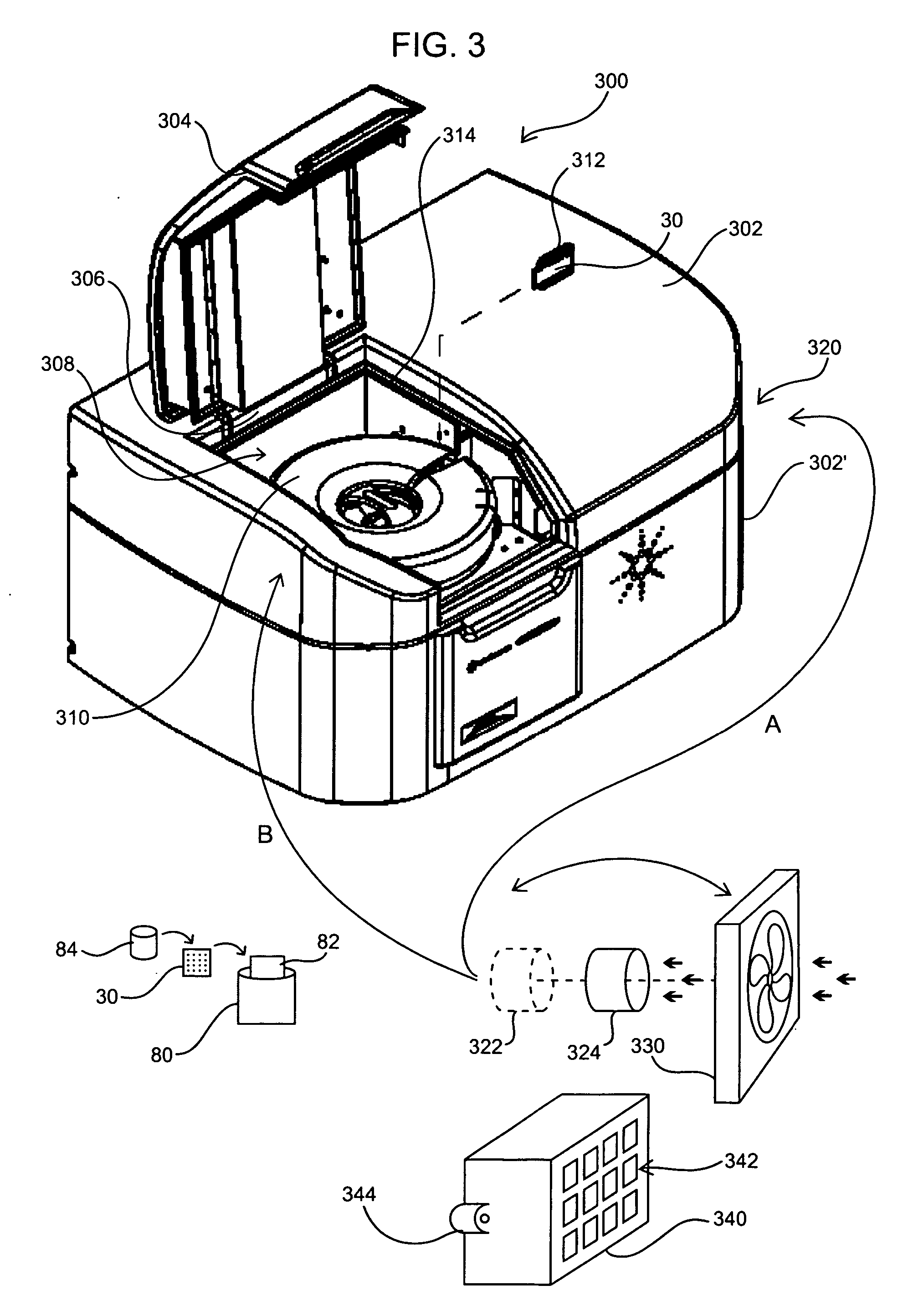
[0040] In describing the invention in greater detail than provided in the Summary and as informed by the Background and Definitions provided above, the pertinent functional aspects of the invention are first described. Next, exemplary components for actually scanning an array are described. This discussion is followed by a brief discussion of methods of using an array as will be protected during scanning by features of the invention. Then, a particular hardware implementation of the present invention is set forth. Finally, kits for use with arrays to be used in connection with scanners according to aspects of the present invention are presented.

[0041] Before describing these matters in such detail, however, it is to be understood that this invention is not limited to particular variations set forth and may, of course, vary. Various changes may be made to the invention described and equivalents may be substituted without departing from the true spirit and scope of the invention. In ...


PUM


Abstract

A reader is provided that, itself, addresses the issue of damage or degradation to arrays within the reader by virtue of air exposure. In doing so, experimental variability is reduced, and read / scan signal strength degradation is minimized for arrays / slides scanned or otherwise read toward the end of a run. The subject scanners employ a filter that reduces the amount of chemicals in the air inside the device that are harmful to the array, or the dye on the array. The implementation of adding a chemical filter to the reader device may be such that air is either drawn into or, alternatively, pushed through the filter into the same. It is possible that the entirety of the device may be provided with filtered air, or just the region holding slides to be scanned. Array readers so-constructed as well as associated methodology involving filtering incoming air while reading arrays are covered.

Description

FIELD OF THE INVENTION [0001] This invention relates to arrays, such as polynucleotide or other biopolymer arrays (for example, peptide arrays). BACKGROUND OF THE INVENTION [0002] Array assays between surface bound binding agents or probes and target molecules in solution may be used to detect the presence of particular analytes or biopolymers in the solution. The surface-bound probes may be oligonucleotides, peptides, polypeptides, proteins, antibodies or other molecules capable of binding with target biomolecules in the solution. Such binding interactions are the basis for many of the methods and devices used in a variety of different fields, e.g., genomics (in sequencing by hybridization, SNP detection, differential gene expression analysis, identification of novel genes, gene mapping, finger printing, etc.) and proteomics. [0003] One typical array assay method involves biopolymeric probes immobilized in an array on a substrate such as a glass substrate or the like. A solution co...

Claims


Application Information

Patent Timeline
IPC IPC(8): G01N21/00G01N21/15
CPCY10T436/212G01N21/15
Inventor CORSON, JOHN F.PARKER, RUSSELL A.
Owner AGILENT TECH INC
Learn More