
Living body light measurement system and signal processing method

a technology of light measurement system and living body, applied in the field of living body light measurement system, can solve the problems of limited number of optical fibers and difficulty in simulation, and achieve the effect of improving accuracy

Inactive Publication Date: 2005-09-01
HITACHI LTD
View PDF3 Cites 26 Cited by
  • Summary
  • Abstract
  • Description
  • Claims
  • Application Information

AI Technical Summary

Benefits of technology

[0041] Since the brain activation area can be estimated with a location accuracy which is higher than the conventionally achieved accuracy, diagnosis for the diseased areas of the brain and medical treatments based on the results of these diagnoses can be realized with improved accuracy.

Problems solved by technology

However, the ability to increase the number of optical fibers is limited because the number of optical fibers gives influence on the structure of the helmet.
However, it is difficult to realize the simulation by changing all of the numerous parameters.

Method used


Image

  • Living body light measurement system and signal processing method
  • Living body light measurement system and signal processing method
  • Living body light measurement system and signal processing method

Examples


Embodiment Construction

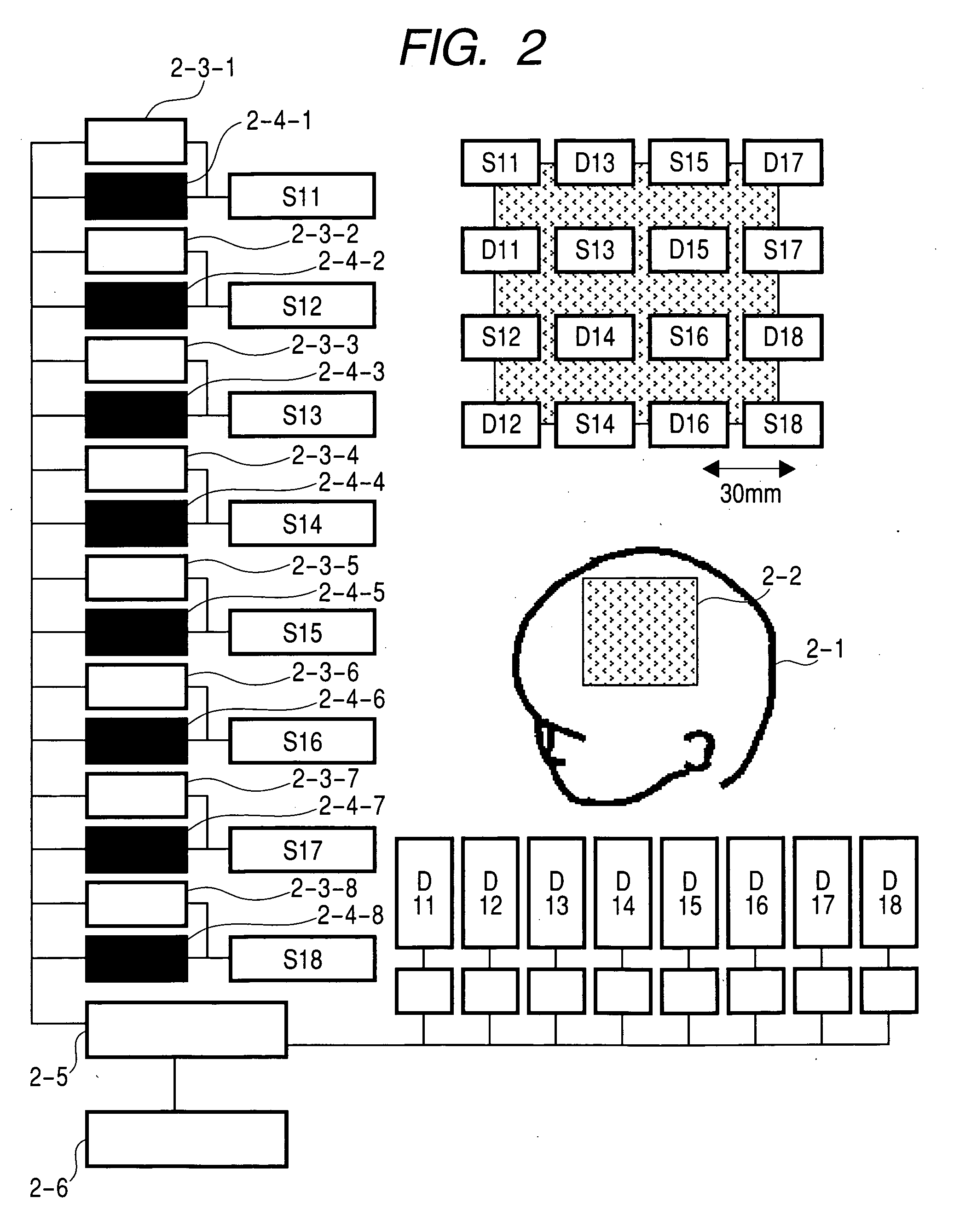
[0064] In a first preferred embodiment of the present invention, a distribution of displacements illustrated in FIG. 11 is initially stored directly within a storage device (e.g., a memory or hard disk drive) provided in a computer 2-5 which includes a display illustrated in FIG. 2. Moreover, this distribution may also be stored in a storage device in the computer 2-5 using an information storage medium such as a CD-ROM.

[0065] The present invention includes several methods of compensating for the distribution of displacements illustrated in FIG. 11 and the results obtained from testing various methods are provided herein.

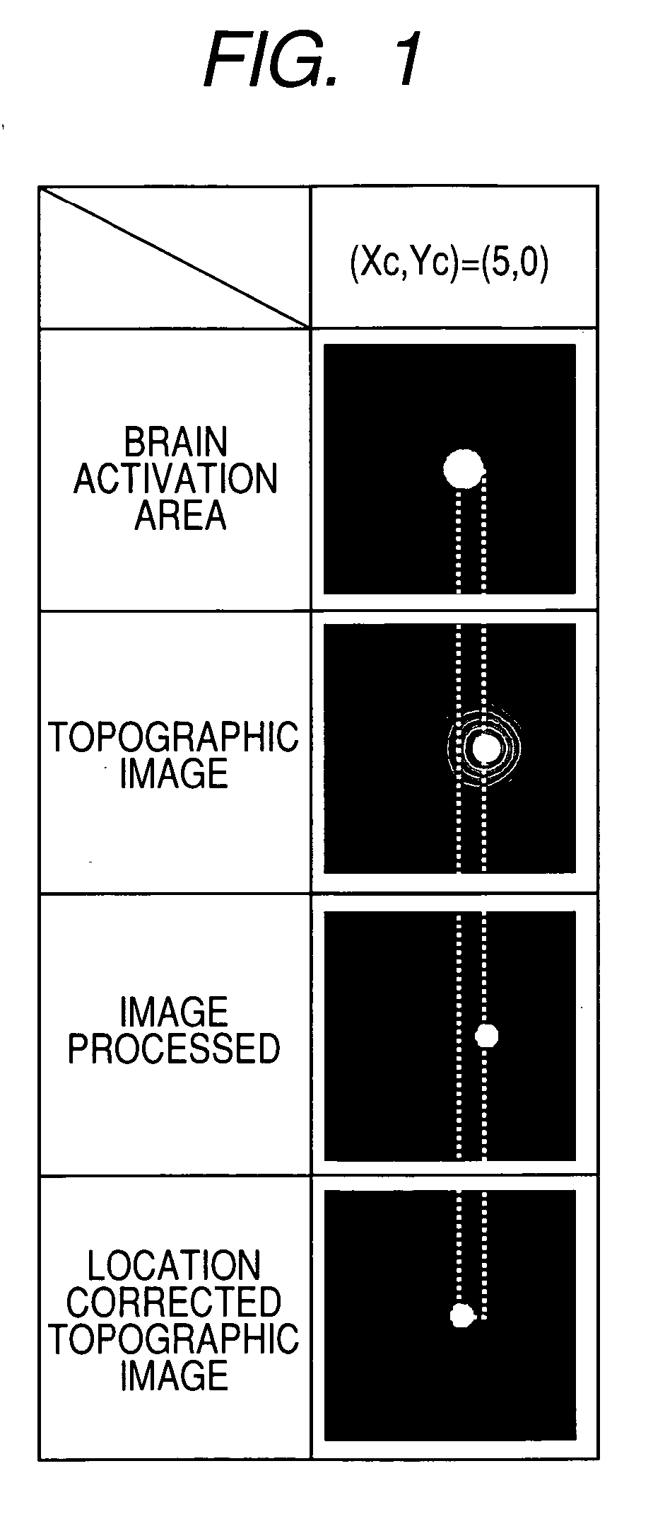
[0066] In a first method, pixels of a topographic image which are spatially distributed are compensated in accordance with distribution of displacements illustrated in FIG. 11. Validity of this method will be discussed with reference to FIG. 12, FIG. 13, and FIG. 14. FIG. 12 illustrates the visualized distribution of displacements of FIG. 11 obtained for the entir...


PUM


Abstract

An image generating methodology for displaying brain activation areas with improved accuracy in a living body light measurement system for generating an image of the changes in blood volume of the brain. A spatial intensity distribution of changes in blood volume can be generated by detecting brain activation in many sampling points, and a spatial interpolation process is executed on this data. A threshold process is executed on the distribution to extract the distribution of coordinates having a signal intensity of at least the predetermined threshold. The displacement between the brain activation area and the maximal location of the distribution is stored in a recording unit of the system in order to compensate for the distribution extracted by the threshold process. Accordingly, brain activation areas can be estimated with greater location accuracy, and the diagnosis and medial treatment for brain diseases can likewise be executed with greater accuracy.

Description

CLAIM OF PRIORITY [0001] The present application claims the benefit under 35 U.S.C. § 119 of the earlier filing date of Japanese Patent Application JP 2004-050741 which was filed on Feb. 26, 2004, the content of which is hereby incorporated by reference into the present application. BACKGROUND OF THE INVENTION [0002] 1. Field of the Invention [0003] The present invention relates to a living body light measurement system, and, more particularly, the present invention is directed to a method for displaying images indicating a special distribution of changes in concentration and a method for displaying such images in a living body light measurement system capable of measuring the concentration of metabolic substances of a living body or the changes in the concentration using the light of the living body. [0004] 2. Description of the Background [0005] Diagnosis of diseases in the brain can be realized by measuring, when possible, the activation of the human brain. Moreover, recovery pro...

Claims


Application Information

Patent Timeline
IPC IPC(8): A61B5/00G01N21/17A61B10/00
CPCA61B5/14553A61B2562/046A61B2562/0233A61B5/0042
Inventor YAMAMOTO, TSUYOSHIMAKI, ATSUSHIKATURA, TAKUSIGEKAWAGUCHI, HIDEO
Owner HITACHI LTD
Learn More