Method and apparatus for needle-less injection with a degassed fluid

Inactive Publication Date: 2005-09-01
PENJET CORP
View PDF99 Cites 125 Cited by
  • Summary
  • Abstract
  • Description
  • Claims
  • Application Information

AI Technical Summary

Benefits of technology

[0024] It is therefore an object of an embodiment of the instant invention to provide gas-pressured needle-less injectors that obviate, for practical purposes, the above-mentioned limitations.
[0025] The present invention relates to apparatuses and methods for administering a needle-less injection of a degassed fluid. The fluid may be degassed by any number of methods, such as any of those described in U.S. patent application Ser. No. 09/808,511, filed Ma

Problems solved by technology

In addition, the traditional method of intradermal injections requires actual physical contact and penetration of a needle through the skin surface of the patient, which can be painful for the patient.
Traditional needle injectors, such as hypodermic syringes, are also expensive to produce and difficult to use with prepackaged medication doses.
Needle injectors also suffer from increased danger of contamination exposure to health care workers administering the injections, and to the general public when such injectors are not properly disposed of.
However, not only are conventional jet injectors cumbersome and awkward, but, existing conventional jet injectors are only capable of subcutaneous delivery of a medication beneath the skin layers of a patient.
Conventional jet injectors are also somewhat dangerous to use, since they can be discharged without being placed against the skin surface.
In addition, jet injectors that have not been properly sterilized are notorious for creating infections at the injection site.
Moreover, if a jet injector is not positioned properly against the injection site, the injection can result in wetting on the skin surface.
Problems associated with improper dosage amounts may arise as well, if some portion of the fluid intended for injection remains on the skin surface following an injection, having not been properly injected into and/or through the skin surface.
Subdermal hematomas, tissue damage, and scarring from mechanical force injury may result from the use of needle-less injectors when pockets of gas are present in the injector ampoule prior to dispensing the medication contained therein.
Thus, gas pockets accelerated against the skin lead to the formation of a bruise and can be quite painful for the recipient, whereas liquid medication passes into and/or through the skin without discomfort.
Further, when a cap is removed from the end of a needle-less injector, exposing the dispensing area for

Method used


Image

  • Method and apparatus for needle-less injection with a degassed fluid
  • Method and apparatus for needle-less injection with a degassed fluid
  • Method and apparatus for needle-less injection with a degassed fluid

Examples


example 1

Modular Gas-Pressured Needle-Less Injector

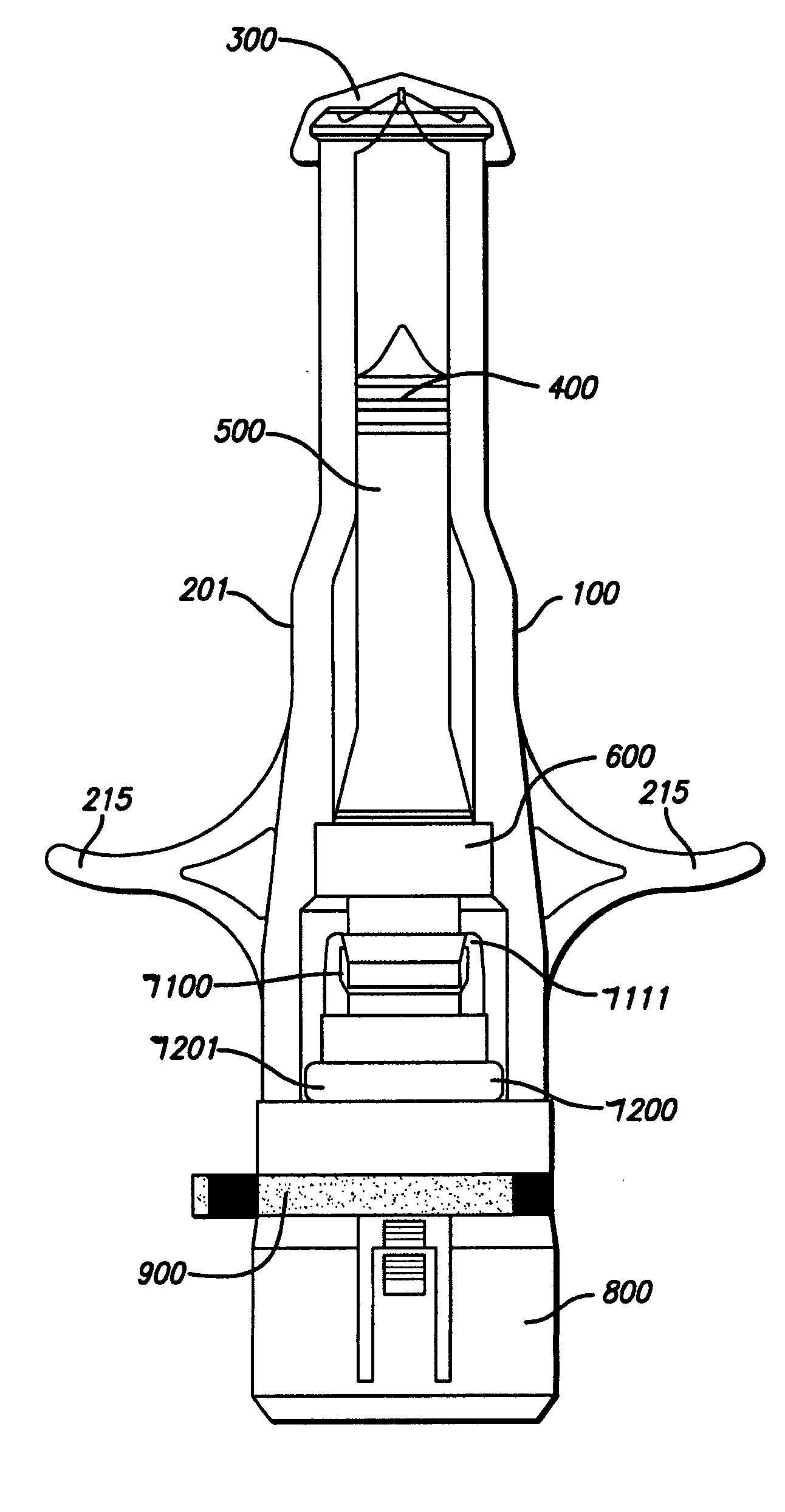
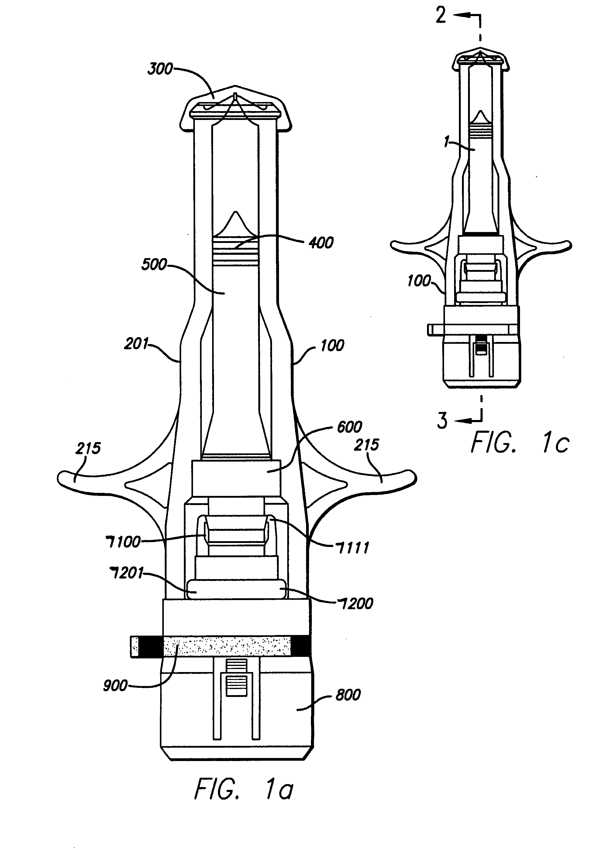
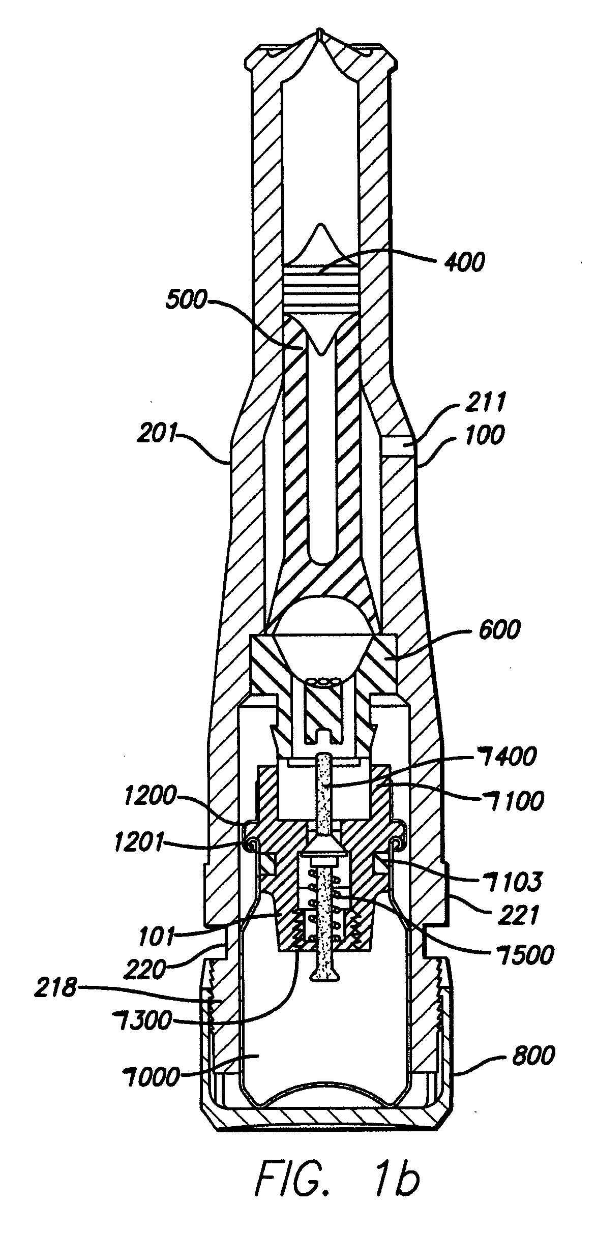
[0052] For ease in describing the various elements of the modular gas-pressured needle-less injector, the following spatial coordinate system will apply thereto. As depicted in FIG. 1c, a central axis is defined through the length of a gas-pressured needle-less injector 100. This central axis 1 has one terminus at the proximate end 2 of the needle-less injector 100, defined as that end of the device in contact with an injection surface during normal operation of the injector. The other terminus of the central axis is at the distal end 3 of the injector 100, defined as that end of the device furthest from the injection surface when the injector is positioned perpendicular to the injection surface. Thus, various elements of the device of the instant invention may be described with reference to their respective proximate and distal portions, as well as their central axes.

[0053] As depicted in FIG. 1, a gas-pressured needle-less injector 100 i...

example 2

Gas-Powered Needle-Less Injector

[0094] As depicted in FIG. 17, the needle-less injector 1000 may be used as a single dose disposable injector to deliver a dosage of degassed fluid. Precise delivery may be achieved through an orifice with a diameter of approximately 0.0032″ (approximately 0.08 mm). However, larger or smaller diameters, ranging from 0.05 mm to 1.5 mm, may be used, as long as accurate penetration of the skin and delivery of the degassed fluid can be maintained. The degassed fluid is linearly accelerated via pneumatic propulsion. Safety is maintained and inadvertent activation of the needle-less injector 1000 is avoided via a pressure (e.g., resistance) sensitive triggering feature which allows for proper tensioning of the nozzle and orifice at the injection site prior to automatic medication deployment. For example, activation of the needle-less injector 1000 will not occur until the injector is properly positioned to provide the required resistance from the skin surf...

example 3

Needle-Less Injector Including a Latch

[0102] As depicted in FIG. 26, a needle-less injector comprises a tubular body 2001, which retains a cartridge 2003 pre-filled with a degassed fluid, and visible through one or more windows 2004 in the body 2001. The body 2001 has an aperture in the end to permit a nozzle 2005 to protrude. A finger nut 2006 is used by the operator to control the dose volume, and has markings 2007 thereon to indicate its position relative to a scale 2008 on sliding sleeve 2002, which is arranged co-axially on the body 2001.

[0103] In FIG. 27, the cartridge 2003 is shown filled with degassed fluid 2009, and fitted with a nozzle 2005 having an orifice 2010, and a free piston 2032. The nozzle 2005 may be a separate component as shown, sealingly fixed into the cartridge 2003, or may be formed integrally with the cartridge 2003. Preferably the cartridge 2003 is made of a transparent material compatible with the degassed fluid 2009, to enable the contents to be viewed...


PUM


Abstract

Apparatuses and methods are described for administering a needle-less injection of a degassed fluid. Prior to filling, or after filling but prior to administration of a needle-less injection, gas is removed from the fluid to create a degassed fluid. A needle-less injection may then be performed with a reduced risk of discomfort to the recipient of the injection and with lower potential for the creation of a subdermal hematoma as a result of the injection. A wide variety of needle-less injectors may be used in accordance with various embodiments of the present invention.

Description

RELATED APPLICATIONS [0001] This application is a continuation-in-part of U.S. patent application Ser. No. 10 / 227,885, filed Aug. 26, 2002. This application is also a continuation-in-part of U.S. patent application Ser. No. 10 / 227,879, filed Aug. 26, 2002, which is a continuation of U.S. patent application Ser. No. 09 / 834,476, filed Apr. 13, 2001, now U.S. Pat. No. 6,613,010, issued Sep. 2, 2003. [0002] This application is related to U.S. patent application Ser. No. 09 / 566,928, filed May 6, 2000, now U.S. Pat. No. 6,447,475, issued Sep. 10, 2002. Further, this application generally relates to U.S. patent application Ser. No. 09 / 215,769, filed Dec. 19, 1998, now U.S. Pat. No. 6,063,053, which is a continuation of U.S. patent application Ser. No. 08 / 727,911, filed Oct. 9, 1996, now U.S. Pat. No. 5,851,198, which is a continuation-in-part of U.S. patent application Ser. No. 08 / 719,459, filed Sep. 25, 1996, now U.S. Pat. No. 5,730,723, which is a continuation-in-part of U.S. patent appl...

Claims


Application Information

Patent Timeline
IPC IPC(8): A61M5/20A61M5/24A61M5/30A61M5/31A61M5/48
CPCA61M5/204A61M5/2053A61M5/2448A61M5/30A61M5/3129A61M5/484A61M2205/583A61M2005/3104A61M2005/3123A61M2005/3142A61M2205/50A61M2205/582A61M2005/2013
Inventor CASTELLANO, THOMAS P.
Owner PENJET CORP
Why Eureka
Try Eureka