Adaptive waveform equalization for viterbi-decodable signal and signal quality evaluation of viterbi-decodable signal

a technology of adaptive equalization and viterbidecodable signal, which is applied in the field of adaptive equalization of the waveform of a reproduced signal, can solve the problems of long start-up time, complex start-up process, and inability to provide the lowest error rate of equalization, so as to achieve simple arrangement, evaluate the quality of the digital signal, and high accuracy

Inactive Publication Date: 2005-09-01
SHARP KK
View PDF12 Cites 47 Cited by
  • Summary
  • Abstract
  • Description
  • Claims
  • Application Information

AI Technical Summary

Benefits of technology

[0035] Further, the second object of the present invention is to provide a signal quality evaluation method and a signal quality evaluation device by which quality of a digital signal can be evaluated based on a path metric difference with a simple arrangement.
[0040] Meanwhile, if the equalization properties are adapted by using the path metric difference, it is possible to take into consideration the error rate upon the adaptation. This is based on the following reason. The path metric difference is an index for determining a correct path out of two paths one of which will be a survivor path in Viterbi decoding. Thus, the path metric difference indicates how likely the equalized signal pattern, on which the detection of the path metric difference is based, will cause an error path to be regarded as the survivor path upon decoding, that is, indicates how often the error will occur upon decoding. Therefore, if the equalization properties are adapted by using the path metric difference, it is possible to take into consideration the error rate upon the adaptation, so that it is possible to achieve a satisfactory result in lowering the error rate caused by decoding.
[0043] As a result, it is possible to realize the waveform equalizing device and the waveform equalization method which can achieve a satisfactory result in lowering the error rate caused by decoding, in accordance with the foregoing arrangement and method.
[0047] Thus, it is possible to calculate the path metric difference (SAM) between the correct path and the error path in Viterbi decoding, so that it is possible to evaluate the quality of the digital signal based on the path metric difference with a simple arrangement. Further, it is not necessary to use the Viterbi decoder upon computing the path metric difference. Therefore, it is possible to evaluate the quality of the digital signal that has not been subjected to the signal process for Viterbi decoding based on the path metric difference.
[0048] Thus, it is possible to evaluate the quality of the digital signal based on the path metric difference with high accuracy without using a complicate Viterbi decoding circuit. Therefore, even in a case of designing a system such as an optical disc reproducing device by using an existing signal processing LSI whose PRML function has been black-boxed, it is not necessary to additionally provide a Viterbi decoding circuit for evaluating the digital reproduced signal.

Problems solved by technology

Thus, the equalization does not always provide the lowest error rate.
The start-up time is therefore long, and the start-up process is complex.
Adaptive equalization through this technique again does not always ensure equalization properties with the lowest error rate.
The adjustment is less effective and hence more difficult to achieve a satisfactory result in lowering the error rate than suitable waveform equalization.
The higher density of the optical disc deteriorates the quality of the reproduced signal read out from the optical disc.
Under such condition, jitter which represents irregularities in a direction of a time base is not suitable as an evaluation value.
Further, a bit error rate of a data detection result that has been obtained by PRML is used as the evaluation value, but this brings about many disadvantages as follows: a large number of sample bits are required upon measurement, and defects caused by flaws of a disk tend to influence the evaluation, and other similar disadvantages are brought about.
Because of the presence of various kinds of noise in the reproduced signal, there are irregularities in the ideal values.
However, the conventional arrangement brings about the following disadvantages: it is necessary to realize the foregoing Viterbi decoding circuit to calculate SAM, and it is necessary to make a new arrangement for determining which ΔM should be selected from the equation (33) as SAM corresponding to the correct bit pattern, so that the circuit is complicated.
Further, in case of designing a system of a reproducing device for a storage medium by using an existing signal processing LSI whose PRML function has been black-boxed, it is impossible to calculate SAM.

Method used


Image

  • Adaptive waveform equalization for viterbi-decodable signal and signal quality evaluation of viterbi-decodable signal
  • Adaptive waveform equalization for viterbi-decodable signal and signal quality evaluation of viterbi-decodable signal
  • Adaptive waveform equalization for viterbi-decodable signal and signal quality evaluation of viterbi-decodable signal

Examples


embodiment 1

[0075] The following will describe a first embodiment of the present invention with reference to FIGS. 1 to 10.

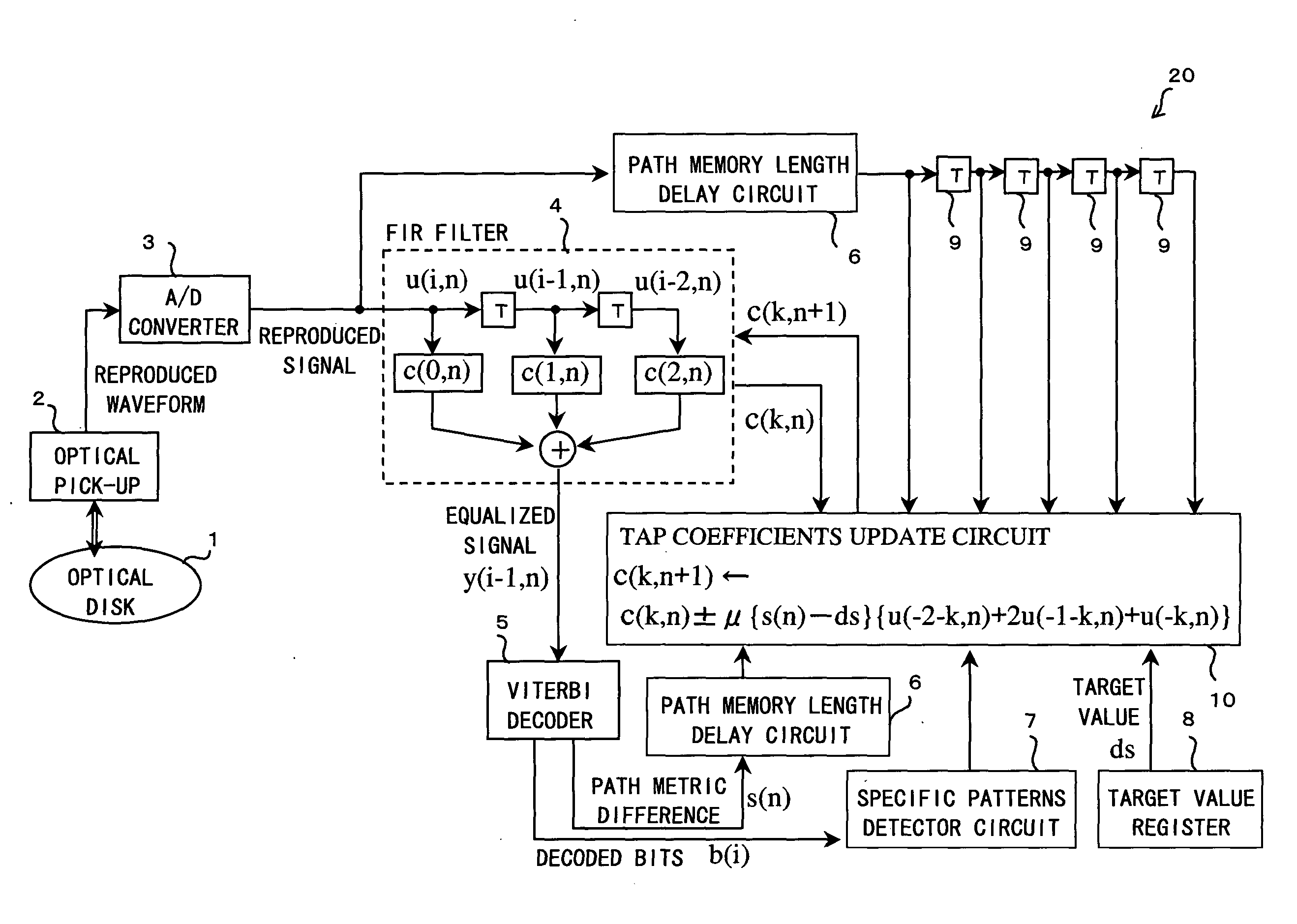
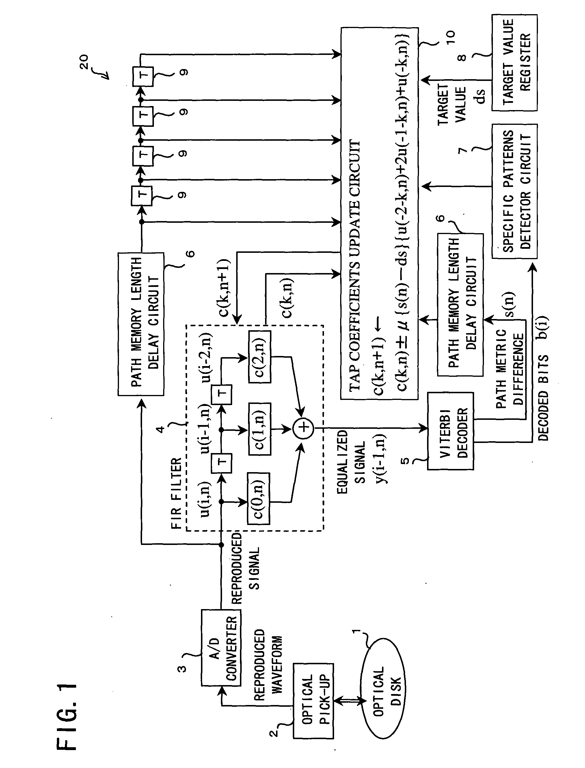
[0076]FIG. 1 is a block diagram showing an arrangement of an optical disc reproducing device (information reproducing device) 20 incorporating a waveform equalizing device according to the present invention. The optical disc reproducing device 20 reproduces data on an optical disc 1 and includes an optical pickup 2, A / D converter 3, FIR filter 4, Viterbi decoder 5, path memory length delay circuits 6, specific patterns detector circuit 7, target value register 8, T-delay elements 9 (T here and in the following description refers to one channel bit time of a reproduced signal), and tap coefficients update circuit 10.

[0077] The optical disc 1 has a mark pattern recorded thereon based on d=1 RLL (Run Length Limited) coding, such as S(1,7) RLL coding, that is, modulation with the shortest mark length of 2T.

[0078] The optical pickup (reproduction means) 2 reproduces an analog...

embodiment 2

[0168] The following will describe a second embodiment of the present invention with reference to FIG. 11. Here, for convenience, members of the present embodiment that have the same arrangement and function as members of embodiment 1, and that are mentioned in that embodiment are indicated by the same reference numerals and description thereof is omitted.

[0169] An optical disc reproducing device 21 of the present embodiment adjusts equalization properties using an optical disc 1′ on which a known bit pattern is stored. The known bit pattern is stored as a reference bit pattern in a reference bit pattern memory 11. The optical disc 1′ is assumed to have an equalization properties adjusting track in which the known bit pattern is stored.

[0170] When the known bit pattern is reproduced from the optical disc 1′, the same bit pattern b′(i) as the reproduced known bit pattern is fed to the specific patterns detector circuit 7 from the reference bit pattern memory 11 in synchronism with ...

embodiment 3

[0241] The following description will describe a third embodiment of the present invention referring to FIGS. 15 to 20.

[0242] The signal quality evaluation device (circuit) of the present invention evaluates quality of a digital reproduced signal, that has not been subjected to the signal process for Viterbi decoding, according to the path metric difference.

[0243] Thus, the signal quality evaluation device is applicable to a device which performs Viterbi-decoding signal reproduction, or a device which does not actually perform the signal reproduction but is based on the Viterbi-decoding reproduction. That is, the signal quality evaluation device can be preferably installed to an optical disc reproducing device, a magnetic recording / reproducing device such as a hard disk device and a magnetic tape device, and a communication data receiving device. For example, if the signal quality evaluation device is installed to the optical disc reproducing device in combination with a controlli...


PUM

PropertyMeasurementUnit
weightsaaaaaaaaaa
memory lengthaaaaaaaaaa
thresholdaaaaaaaaaa

Abstract

The waveform equalizing device includes: an FIR filter for generating an equalized signal pattern y(i, n) on the basis of equalization of a waveform of the reproduced signal pattern u(i, n); a Viterbi decoding circuit for detecting a path metric difference s(n) between a correct path determined as a survivor path and an error path which fails to survive the correct path in Viterbi decoding based on the equalized signal pattern y(i, n); a target register for setting a target value ds for the path metric difference s(n); and a tap coefficients update circuit for adapting the equalization according to an error of the detected path metric difference from the target value. The tap coefficients update circuit adapts equalization properties so that the mean square error is minimized, thereby achieving a satisfactory result in lowering the error rate.

Description

FIELD OF THE INVENTION [0001] The present invention relates to a waveform equalizing device, method, and program for adaptive equalization of the waveform of a reproduced signal in a signal reproduction system; a computer-readable storage medium with the waveform equalization program stored thereon; and an information reproducing device and communications device incorporating the waveform equalizing device. [0002] Further, the present invention relates to a PRML (Partial Response Maximum Likelihood) signal process, and more specifically to a signal quality evaluation method for evaluating quality of a Viterbi-decoded digital signal, a signal quality evaluation device and a reproduction apparatus having the same, a signal quality evaluation program and a computer-readable storage medium having the same. BACKGROUND OF THE INVENTION [0003] PRML (Partial Response Maximum Likelihood) has been adopted as a data detection method to provide information storage media (hereinafter, simply “st...

Claims


Application Information

Patent Timeline
Patent Type & Authority Applications(United States)
IPC IPC(8): G11B20/10H03M13/03H04L25/03
CPCG11B7/1263G11B20/10009G11B20/10046H04L2025/03617G11B20/10481H04L25/03038G11B20/10101
Inventor OKUMURA, TETSUYAMAEDA, SHIGEMI
Owner SHARP KK
Why Eureka
Try Eureka