Liquid fuel nozzle apparatus with passive water injection purge

a technology of liquid fuel nozzle and purge, which is applied in the direction of lighting and heating apparatus, engine ignition, engine/propulsion engine, etc., can solve the problems of thermal distress of the fuel nozzle, the inability to open the possibility of ingesting combustion gases, and the inability to set the time-period. practicable, however, to achieve the effect of shortening the time-period

Inactive Publication Date: 2005-09-08
GENERAL ELECTRIC CO
View PDF5 Cites 31 Cited by
  • Summary
  • Abstract
  • Description
  • Claims
  • Application Information

AI Technical Summary

Benefits of technology

[0008] The above discussed and other drawbacks and deficiencies are overcome or alleviated in an exemplary embodiment by a liquid fuel nozzle assembly having a passive protective purge in place of a dedicated active purge in order to protect the nozzle from damage during periods when water is not flowing through the water passageway of the nozzle.
[0009] In accordance with one embodiment of the present invention, there is provided an apparatus and method for purging a liquid fuel nozzle and protecting the same from back-flowing combustion gases during a transition period when neither liquid fuel nor active purge are flowing through the nozzle. Specifically, a gas turbine includes a compressor, a combustor and a turbine, a liquid fuel unit for flowing liquid fuel into the combustor via a nozzle assembly. The nozzle assembly includes passageways for flowing a liquid fuel, water injection and high pressure air, respectively, into the combustor; a conduit interconnecting the water injection passageway and the high pressure air passageway enabling diversion of at least a portion of the high pressure air flow from the high pressure air passageway into the water injection passageway via the conduit to protect the nozzle from ingestion of hot combustor gases; a first swirler arranged in the water injection passageway; and a first end of the conduit being coupled to the water injection passageway downstream of the first swirler and an opposite second end of the conduit being in communication with the high pressure air passageway, the first end of the conduit being in communication with the water injection passageway downstream of the first swirler.
[0010] In another embodiment, a method for operating a dual fuel gas turbine having a combustor, a compressor and a turbine is disclosed. The method includes supplying liquid fuel to the combustor via a nozzle having a plurality of passageways, one of the passageways being a water injection passageway; interconnecting the water injection passageway to one of the plurality of passageways via a conduit to enable fluid flow therebetween, the one of the plurality of passageways flowing high pressure air; and protecting the nozzle from ingestion of backflow combustion gases by diverting high pressure air from the one of the plurality of passageways into the water injection passageway via the conduit.
[0012] In yet another aspect, in a dual-fuel gas turbine having a compressor, a combustor and a turbine, a method of passively protecting a liquid fuel nozzle is disclosed. The method includes flowing a liquid fuel, water injection, and atomizing air into the combustor via respective nozzle passageways; coupling the water injection and the atomizing air passageways to one another via a conduit; diverting at least a portion of high pressure air from the atomizing air passageway into the water injection passageway to protect the nozzle from ingestion of hot combustor gases; disposing first and second swirler units for the water injection and atomizing air passageways, respectively, adjacent exit ends thereof; coupling a first end of the conduit to the water injection passageway at a location downstream of the first swirler unit in the water injection passageway; and coupling an opposite second end of the conduit to the atomizing air passageway at a location upstream of a second swirler unit in the atomizing air passageway.

Problems solved by technology

This sequence results in a brief period during which there is neither fuel / water flow nor purge air, thus opening the possibility of ingesting combustion gases into the fuel nozzle assembly.
The brief no-flow period may also cause thermal distress of the fuel nozzle.
There are practical limits, however, as to how short this time-period can be set.
Also, flowing purge air quickly into a fuel system that is full of fuel due to a prior operation may force the left over fuel into the combustor and produce an undesirable surge in turbine output.
The flowing of purge air quickly into a water system that is full of water due to prior operation, may force the left over water into the combustions system in this case producing the undesirable flaming out of the combustion system.
This approach, however, is not only difficult to implement but also includes performance side effects.
The systems that control the air purges and liquid flows are both complex and expensive.

Method used


Image

  • Liquid fuel nozzle apparatus with passive water injection purge
  • Liquid fuel nozzle apparatus with passive water injection purge
  • Liquid fuel nozzle apparatus with passive water injection purge

Examples


Embodiment Construction

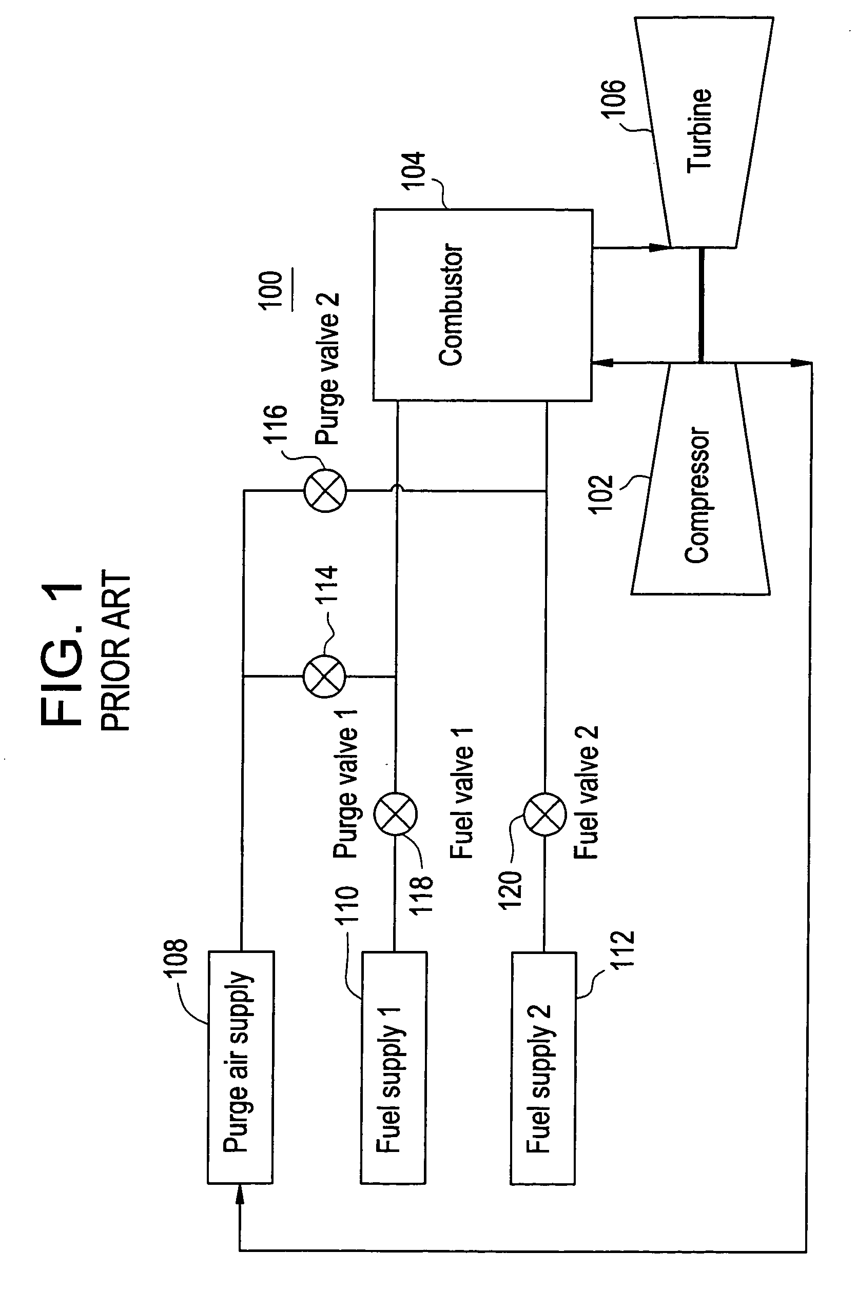
[0021]FIG. 1 shows schematically a gas turbine 100 having a compressor 102, a combustor 104, and a turbine 106. The gas turbine 100 further includes a purge air supply system 108, a first fuel supply system 110, and a second fuel supply system 112. Fuel valves 118, 120 regulate supply of fuel from first and second fuel supply systems 110, 112, respectively. Similarly, purge valves 114, 116 regulate the supply of purge air from the purge air supply system 108 to supply lines carrying fuel from fuel supply systems 110, 112, respectively, into the combustor 104.

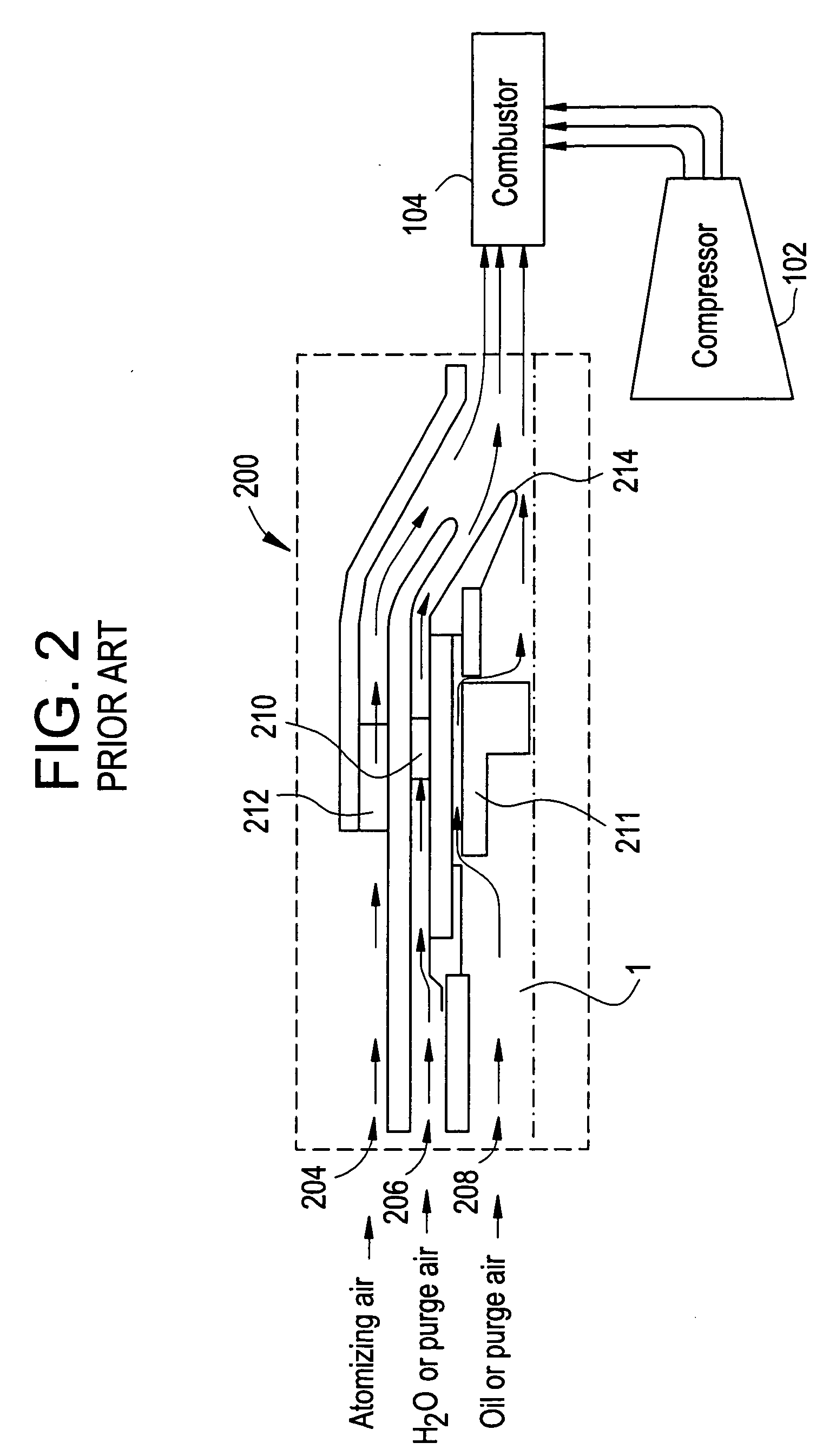
[0022]FIG. 2 shows a cross-sectional view of a conventional liquid fuel nozzle cartridge 200 having three-passageways 204, 206, 208 for flowing fluids into combustor 104. The first passageway 204 flows atomizing air into combustor 104, the second passageway 206 flows water or purge air into the combustor 104, and the fuel passageway 208 flows liquid fuel or purge air into the combustor. Each of the three passageways 204, 206, a...


PUM


Abstract

In a gas turbine having a compressor, a combustor and a turbine, a gaseous fuel supply coupled to provide gaseous fuel to the combustor, a liquid fuel supply coupled to provide liquid fuel to the combustor via nozzle assembly. The nozzle assembly includes a plurality of passageways for flowing a fluid into the combustor, one of the passageways being an atomizing air passageway conduit interconnecting the atomizing air passageway to one of the plurality of passageways to enable fluid flow therebetween, while not allowing the flow of fluid back into the atomizing air passageway. High pressure air from the atomizing air passageway is diverted into one of the plurality of passageways via the conduit to protect the nozzle from ingestion of hot combustor gases, thus eliminating a need for a dedicated air purge system for that one of the plurality of passageways.

Description

BACKGROUND OF THE INVENTION [0001] This invention relates to gas turbines, and more particularly, to a liquid fuel nozzle assembly having a passive protective purge for protecting the nozzle from damage when neither water nor active purge is flowing through the water passageway of the nozzle. [0002] Industrial gas turbines often are capable of alternatively running on liquid and gaseous fuels. These gas turbines have fuel supply systems for both liquid and gas fuels, e.g., natural gas. The gas turbines generally do not simultaneously burn both gas and liquid fuels. Rather, when the gas turbine burns liquid fuel, the gas fuel supply is turned off and vice-versa. The fuel / water system that is not being used is usually purged with air. [0003] Gas turbines that burn liquid fuels require a liquid fuel purge system to clear combustor fuel nozzles of liquid fuel. Air is typically used to actively purge unused combustor nozzle passages during turbine operation. Purge air supplied from an ex...

Claims


Application Information

Patent Timeline
Patent Type & Authority Applications(United States)
IPC IPC(8): F02C7/22
CPCF02C3/22F02C3/24F02C3/30F02C7/22F23R3/28F23D11/106F23D2206/10F23D2209/30F23L7/002F05D2260/10
Inventor IASILLO, ROBERT J.MICK, WARREN JAMES
Owner GENERAL ELECTRIC CO
Why Eureka
Try Eureka