Mounting system inserted between an aircraft engine and a rigid structure of an attachment strut fixed under a wing of this aircraft

a technology of rigid structure and mounting system, which is applied in the direction of power plant arrangement/mounting, aircraft power plant construction, etc., can solve the problems of reducing the life of the engine and its performance, significant longitudinal bending of the engine, and inevitably occurring high friction, so as to reduce the size of the mounting system

Active Publication Date: 2005-09-08
AIRBUS OPERATIONS (SAS)
View PDF6 Cites 40 Cited by
  • Summary
  • Abstract
  • Description
  • Claims
  • Application Information

AI Technical Summary

Benefits of technology

[0048] Advantageously, the above mentioned connection also provides a means of canceling out the torque about the transverse axis and longitudinal bending of the engine when it is operating in reverse thrust mode.
[0049] Preferably, the forward compartments of the two lateral actuators are hydraulically connected, and the aft compartments of these two actuators are also hydraulically connected. Consequently, the connections made assure that forces passing through each of the two rods of the lateral actuators are approximately equal during crui

Problems solved by technology

In a manner known to those skilled in the art, a high aerodynamic force can be created on the engine air inlet under some flight conditions and mainly during take off, thus causing significant longitudinal bending of the engine, namely bending resulting from a torque applied about a transverse axis of the aircraft.
In a first case in which no particular precautions have been taken related to the observed bending, high friction inevitably occurs firstly between the rotating blades of the fan and the fan casing, and secondly between the rotating compressor and turbine blades and the engine central casing.
The main consequence of this friction is then premature engine wear, which naturally reduces the life of the engine and

Method used


Image

  • Mounting system inserted between an aircraft engine and a rigid structure of an attachment strut fixed under a wing of this aircraft
  • Mounting system inserted between an aircraft engine and a rigid structure of an attachment strut fixed under a wing of this aircraft
  • Mounting system inserted between an aircraft engine and a rigid structure of an attachment strut fixed under a wing of this aircraft

Examples


Embodiment Construction

[0070] Firstly, note that elements on FIGS. 1 to 9 showing four preferred embodiments of this invention marked with the same numeric references relate to identical or similar elements.

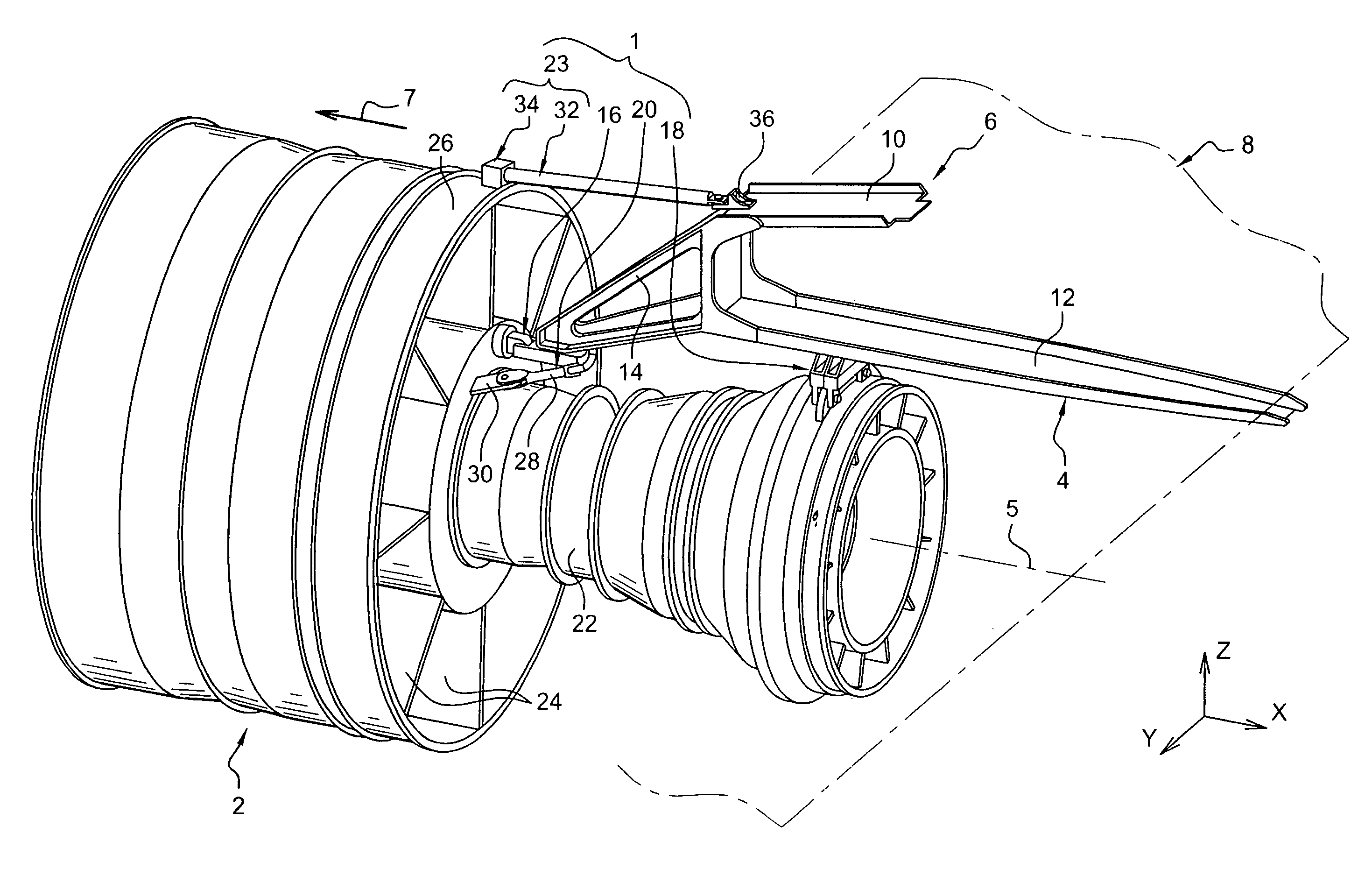
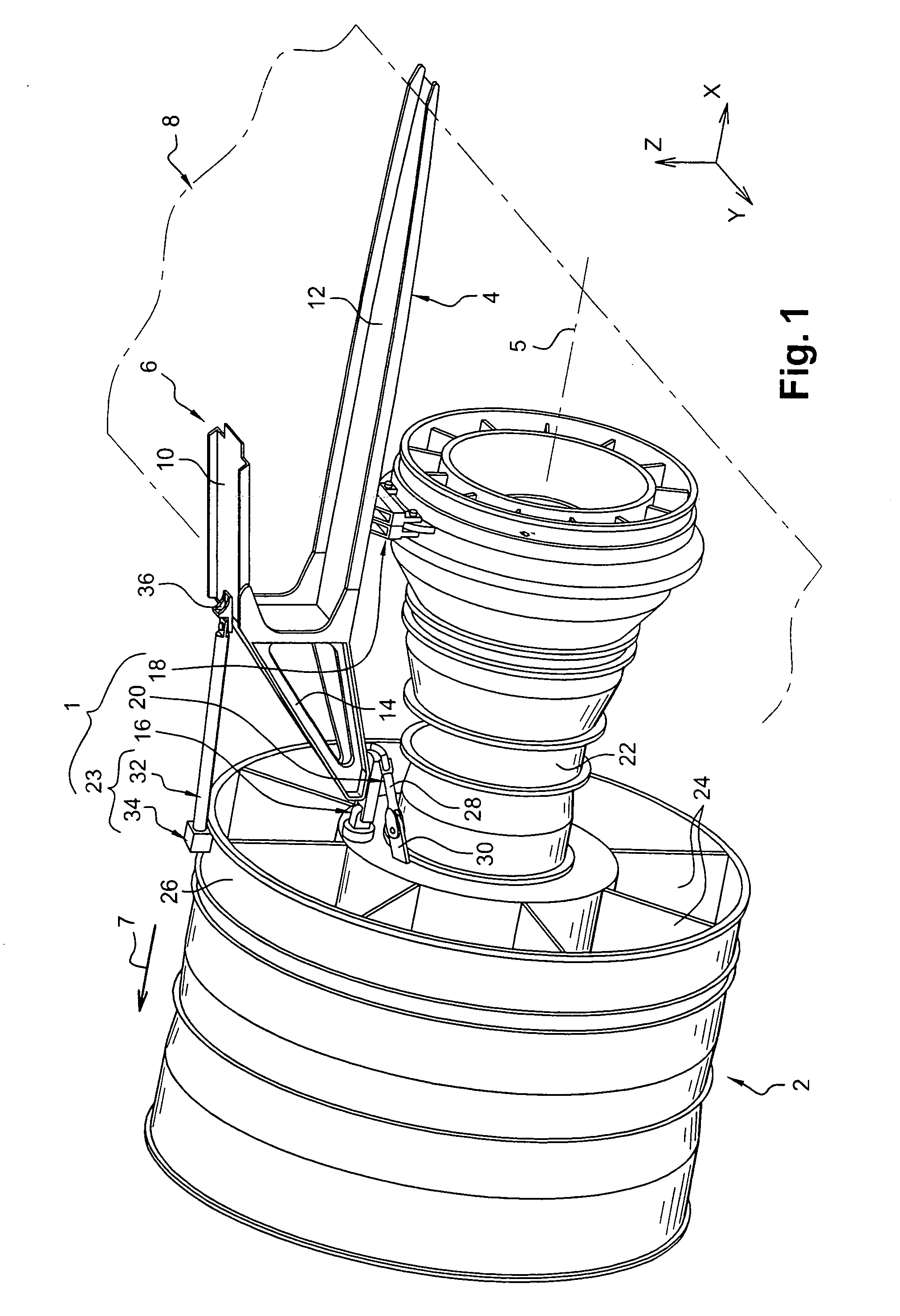
[0071]FIG. 1 shows a mounting system 1 according to a first preferred embodiment of this invention, this mounting system 1 being inserted between an aircraft engine 2 and a rigid structure 4 of an attachment strut 6 fixed under an aircraft wing shown only diagrammatically for obvious reasons of clarity, and denoted generally by the numeric reference 8. Note that the mounting system 1 shown on this FIG. 1 is adapted to cooperate with a turbojet 2, but obviously it could be a system designed to suspend any other type of engine such as a turboprop, without departing from the scope of the invention.

[0072] Throughout the description given below, by convention, X is the direction parallel to a longitudinal axis 5 of the engine 2, Y is the transverse direction of the aircraft, and Z is the vertical directio...


PUM


Abstract

This invention relates to a mounting system (100) inserted between an aircraft engine (2) and a rigid structure (4) of an attachment strut (6) fixed under a wing (8) of this aircraft, the system including a forward mount (16), an aft mount (18) and a device (20, 120, 220) for resisting thrusts generated by the engine (2). The system also comprises additional means (23) for opposing the longitudinal bending of the engine (2), these additional means (23) being designed to resist loads only starting from a predetermined deformation of this engine (2). According to the invention, the additional means (23) comprise at least one connecting rod (32) capable of opposing longitudinal bending of the engine (2), each connecting rod (32) being connected firstly to the rigid structure (4) of the strut (6) and secondly to a fan casing (26) of the engine (2), so that it is only stressed starting from the predetermined deformation of this engine (2).

Description

TECHNICAL DOMAIN [0001] This invention relates in general to a mounting system inserted between an aircraft engine and a rigid structure of an attachment strut fixed under a wing of this aircraft. [0002] The invention also relates to an attachment strut for an aircraft engine fitted with such a mounting system. [0003] The mounting system and the attachment strut as indicated above can be used on any type of aircraft, and more particularly on aircraft equipped with large diameter fan engines. STATE OF PRIOR ART [0004] An aircraft attachment strut is designed to form the connecting interface between an engine and a wing of the aircraft. It transmits forces generated by the associated engine to the structure of this aircraft, and it also enables routing of the fuel, electricity, hydraulics and air between the engine and the aircraft. [0005] In order to transmit forces, the strut comprises a rigid structure, for example of the <<caisson>> type, in other words formed by the a...

Claims


Application Information

Patent Timeline
IPC IPC(8): B64D27/26
CPCB64D2027/264B64D27/26
Inventor MARCHE, HERVE
Owner AIRBUS OPERATIONS (SAS)
Why Eureka
Try Eureka