Device for controlling choke valve of carburetor

a technology of choke valve and carburetor, which is applied in the direction of electrical control, heating types, separation processes, etc., can solve the problems of difficult to achieve both stabilization of engine warm-up operation and improvement of fuel consumption rate, so as to achieve stabilization of warm-up operation and improve fuel consumption rate

Active Publication Date: 2005-09-08
HONDA MOTOR CO LTD
View PDF16 Cites 10 Cited by
  • Summary
  • Abstract
  • Description
  • Claims
  • Application Information

AI Technical Summary

Benefits of technology

[0007] The present invention has been achieved in view of the above-mentioned circumstances, and has an object to provide a simply structured carburetor choke valve control device which ...

Problems solved by technology

Therefore, the opening of the choke valve cannot be always controlled according to changes in engine temperature, so ...

Method used


Image

  • Device for controlling choke valve of carburetor
  • Device for controlling choke valve of carburetor
  • Device for controlling choke valve of carburetor

Examples


first embodiment

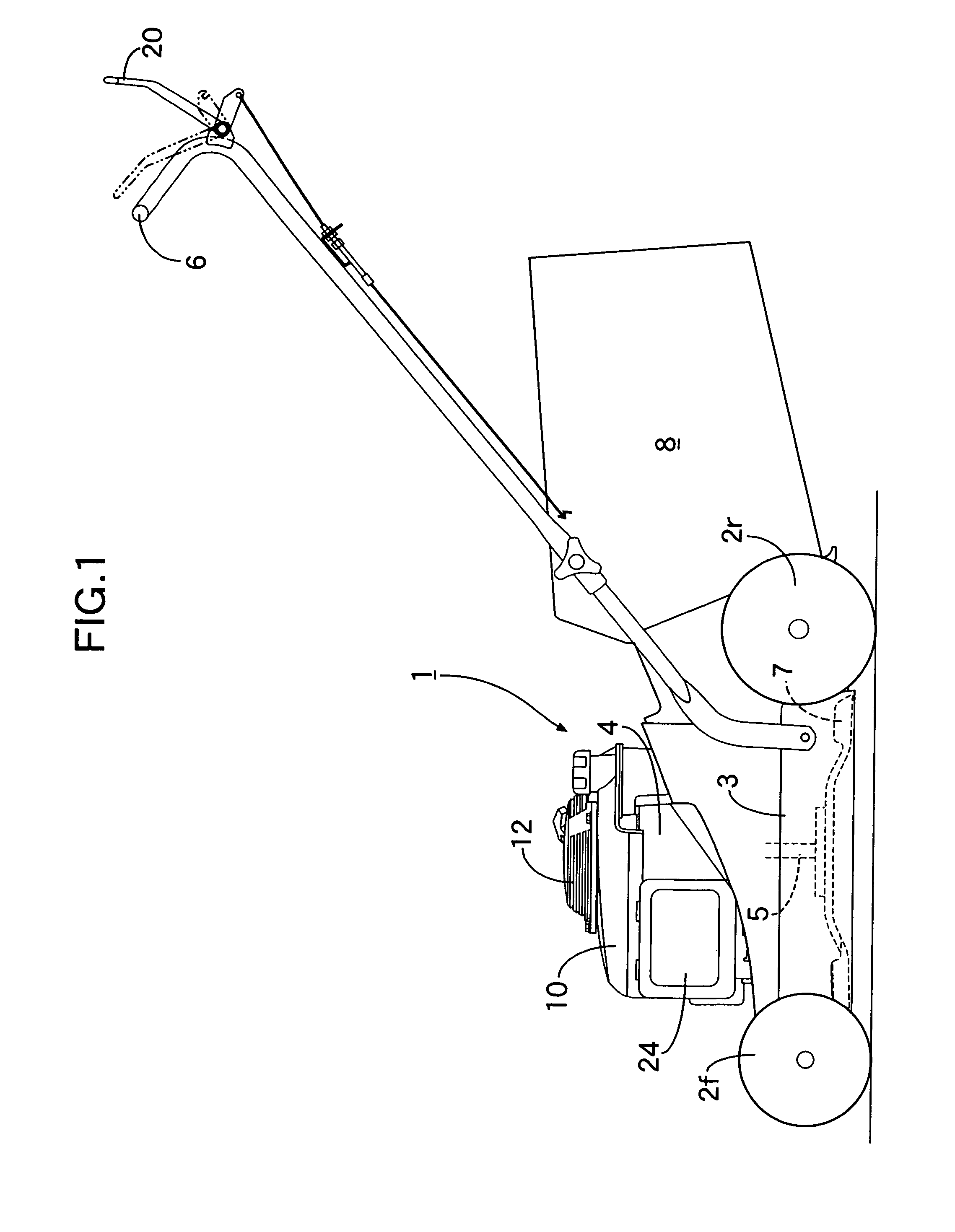
[0044] Description will be first made to the present invention. Referring to FIG. 1, a walking-type lawn mower 1, which is a power working machine, has a housing 3 supported by front wheels 2f and rear wheels 2r. A vertical engine 4 having a crankshaft 5 is mounted on an upper surface of the housing 3, with its crank shaft 5 vertically positioned. Rotary mowing blades 7 are provided in the housing 3 by being attached to the lower end of the crankshaft 5. A glass bag 8 is attached to an operating handle 6 connected to a rear end portion of the housing 3. Lawn grass clipped by the mowing blades 7 is collected in the glass bag 8.

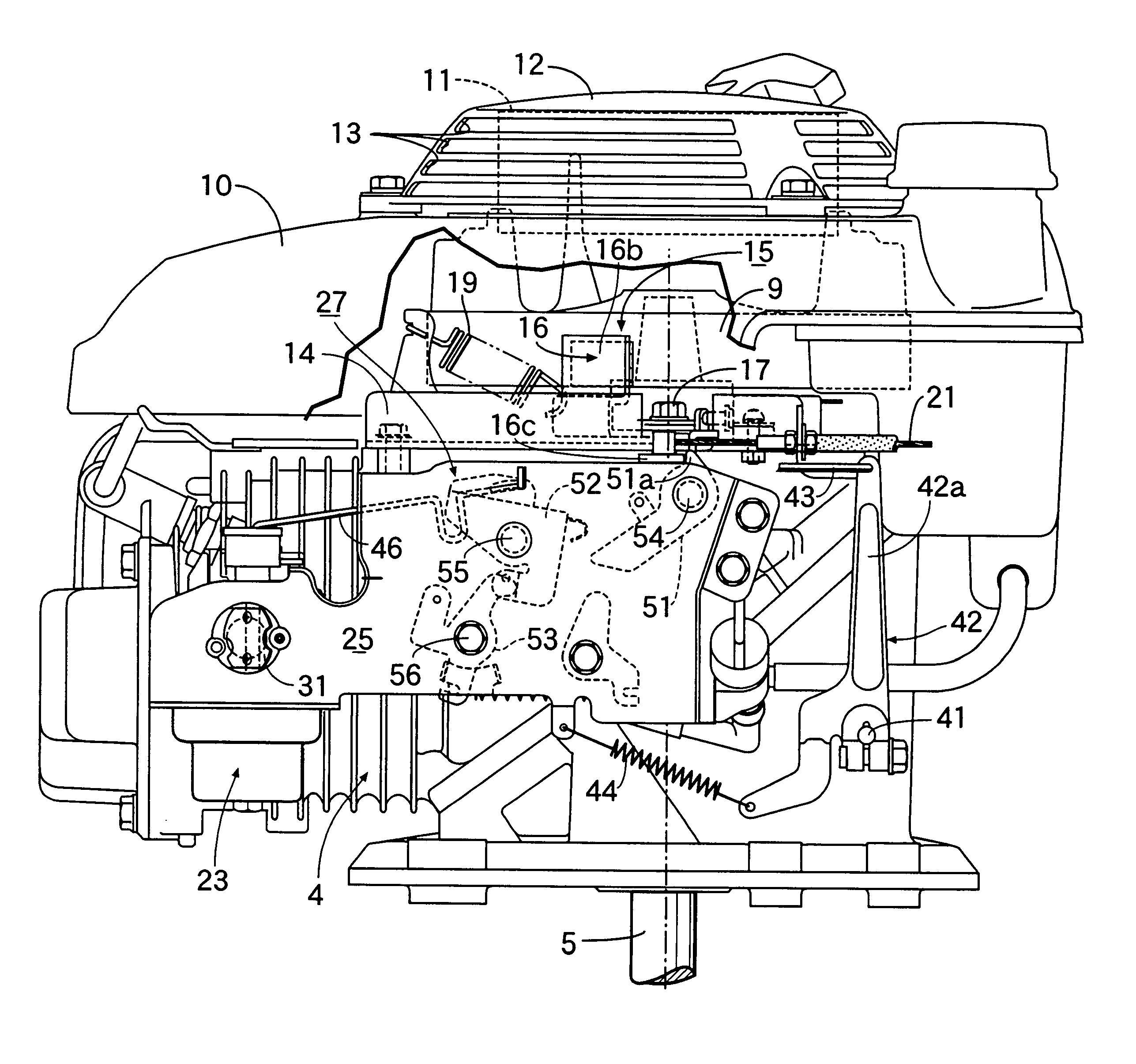
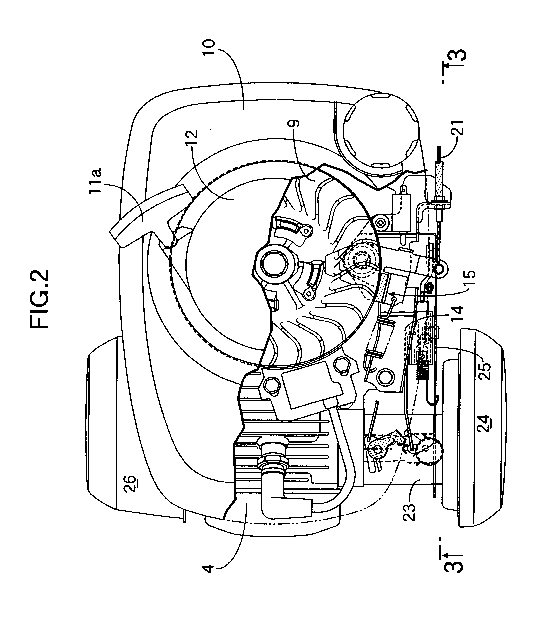
[0045] Referring to FIGS. 2 to 5, a flywheel 9 which functions as a cooling fan is fixed to the upper end of the crankshaft 5 of the engine 4; and an engine cover 10 which, as well as the flywheel 9, covers an upper surface of the engine 4, is fixed on the engine 4. In the engine cover 10, a recoil-type starter 11 capable of driving the crankshaft 5 through the...

second embodiment

[0085] the present invention shown in FIGS. 18A to 18C will be described.

[0086] The second embodiment uses, in the choke valve closed state hold means 72, expansion / contraction of the relief spring 36 (see FIG. 14) in the hub 33a of the choke lever 33 for the vertical movement of the locked arm 50. That is, while each of the lock arm 49 and the locked arm 50 is given rigidity, a sloping surface 61 having a gradient reverse to that in the first embodiment is formed as one side surface of the locked arm 50 formed integrally with the hub 33a. In other respects, the construction is the same as that of the first embodiment. Since the other components are the same as those in the first embodiment, portions corresponding to those in the first embodiment are indicated by the same reference numerals in FIGS. 18A to 18C.

[0087] When the choke lever 33 is turned toward the closing position C by the pulling operation of the brake release lever 20, the sloping surface 61 of the locked ark 50 con...


PUM

PropertyMeasurementUnit
Temperatureaaaaaaaaaa
Speedaaaaaaaaaa

Abstract

A device for controlling a choke valve of a carburetor for an engine includes: a choke closed state hold device for holding, in a closing position, a choke lever urged by a spring in a direction for opening the choke valve, when the choke lever is turned to the closing position, the choke closed state hold device releasing the choke lever from the held state by a throttle operation thereafter performed; a control lever which turns between a low-temperature position and a high-temperature position, and which at its low-temperature position limits the position of the choke lever released from the choke closed state hold device to an intermediate position and at its high-temperature position limits the position of the choke lever to an opening position; a first control spring which urges the control lever toward the low-temperature position; and a second control spring which is made of a shape memory alloy, and which turns the control lever to the high-temperature position when the engine temperature reaches a predetermined high temperature. With this arrangement, the opening of the choke valve is controlled in a rational way according to changes in engine temperature, to thereby stabilize warm-up operation and improve the fuel consumption rate.

Description

RELATED APPLICATION DATA [0001] The Japanese priority application Nos. 2004-58759, 2004-58760, 2004-58761, 2004-116909, 2004-116910 and 2004-116911 upon which the present application is based are hereby incorporated in their entirety herein by reference. BACKGROUND OF THE INVENTION [0002] 1. Field of the Invention [0003] The present invention relates to an improvement in a device for controlling a choke valve of a carburetor in such a manner that a choke lever connected to the choke valve is turned to a closing position corresponding to the completely closed position of the choke valve at a start of the engine, and is automatically turned to a direction for opening the choke valve after the start of the engine. [0004] 2. Description of the Related Art [0005] Japanese Utility Model Laid-Open No. 63-24354 discloses a general carburetor in which a damper and a choke spring which urges a choke lever in an opening direction are connected to the choke lever, the damper automatically opens...

Claims


Application Information

Patent Timeline
IPC IPC(8): F02D9/02F02M1/10
CPCF02D2009/0203F02M1/10F02D2009/0205F02M1/08
Inventor MORIYAMA, HIROSHISUZUKI, TAKASHIARAI, TETSUYASATO, TAKANORI
Owner HONDA MOTOR CO LTD
Why Eureka
Try Eureka