Ophthalmic examination and treatment system

a technology for applied in the field of medical instruments, can solve the problems of difficult use of instruments, difficult installation position, and difficulty in adequate imaging, and achieve the effects of simple and inexpensive ophthalmic examination and treatment, free choice, and no wire crossing

Inactive Publication Date: 2005-09-08
MAKINO OPHTALMIC INSTR
View PDF11 Cites 11 Cited by
  • Summary
  • Abstract
  • Description
  • Claims
  • Application Information

AI Technical Summary

Benefits of technology

[0019] In accordance with the present invention, when a plurality of ophthalmic medical instruments are used in combination, employing a configuration in which wireless communication between wireless imaging devices mounted on respective instruments and a display device conducting display of the image data thereof is conducted by using an ID number allocated in advance to each imaging device makes it possible to conduct displaying from a prescribed imaging device in a prescribed state, without causing wire crossing or the like.
[0020] As described hereinabove, with the ophthalmic examination and treatment system in accordance with the present invention, when a plurality of ophthalmic medical instruments are used in combination, employing a configuration in which wireless communication between wireless imaging devices mounted on respective instruments and a display device conducting display of the image data thereof is conducted by using an ID number allocated in advance to each imaging device makes it possible to conduct displaying from a prescribed imaging device adequately and accurately, without causing wire crossing or the like, and a simple and inexpensive ophthalmic examination and treatment system can be provided.
[0021] In particular, in accordance with the present invention, the advantages that are due to the utilization of a wireless imaging devices, such as freedom in selecting the installation position, transition to adequate captured images, and freedom of instrument transportation can be demonstrated to a greater degree.

Problems solved by technology

A CCD camera has been employed as the aforementioned imaging device in this type of ophthalmic medical instrument, but there is a problem in that a wire-type system where the camera and the display device are connected with a cable is generally employed, making the instrument difficult to use.
Moreover, even upon installing the imaging device in a position in the vicinity of the object to be imaged, since this location is also an important section for the primary instrument, the installation position is easily restricted and cases arise where only such installation is possible in which adequate imaging is difficult.
Moreover, although this is not a serious problem when the aforementioned ophthalmic medical instrument is fixedly installed in an ophthalmic examination room or operating room, a problem arises when the instrument is used as a transportable system in a traveling clinic or the like.
Thus, when there were additional cables for the imaging device, the handling thereof became complicated and the cables were sometimes a hindrance during transportation.
However, in a communication system using wireless communication between the aforesaid wireless CCD camera and a display device receiving the image data signals transmitted from the camera, if the number of cameras or display devices is increased, the system structure becomes complex and there is also a risk of wires getting crossed.
Sharing the display devices can be also considered, but if they operate at the same time, transmission and reception of image data using wireless communication between a camera and a corresponding display device becomes unstable.

Method used


Image

  • Ophthalmic examination and treatment system
  • Ophthalmic examination and treatment system
  • Ophthalmic examination and treatment system

Examples


Embodiment Construction

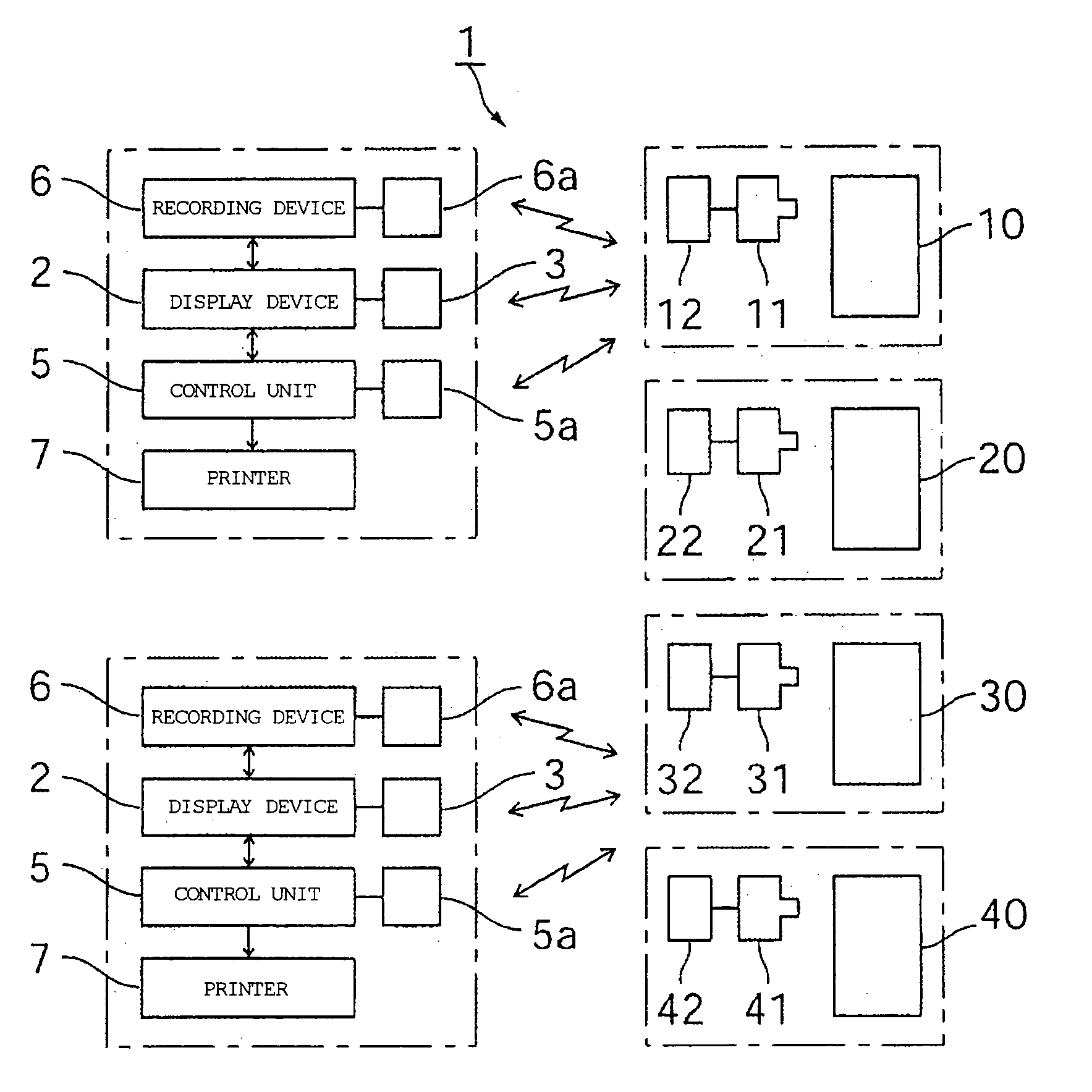
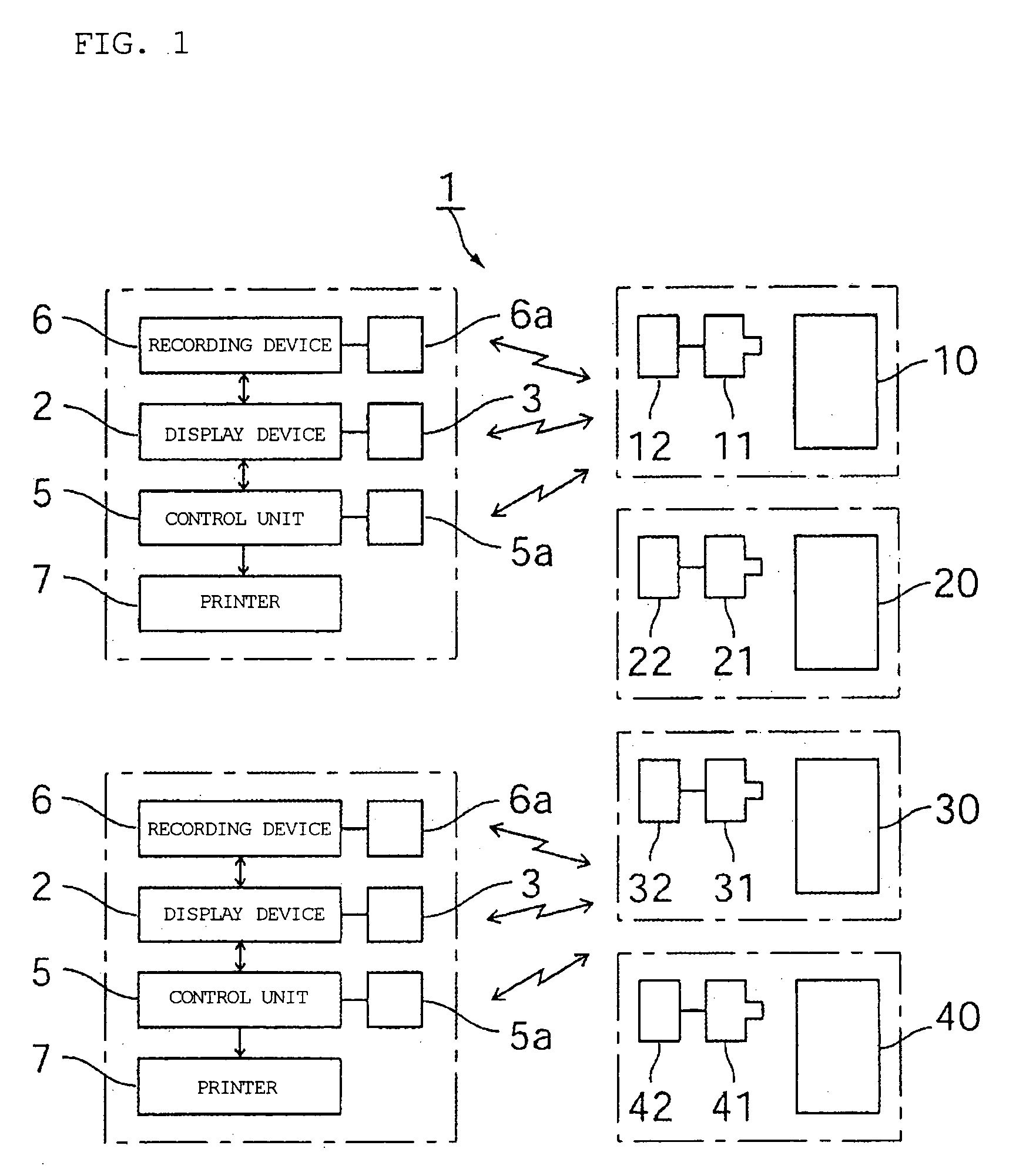
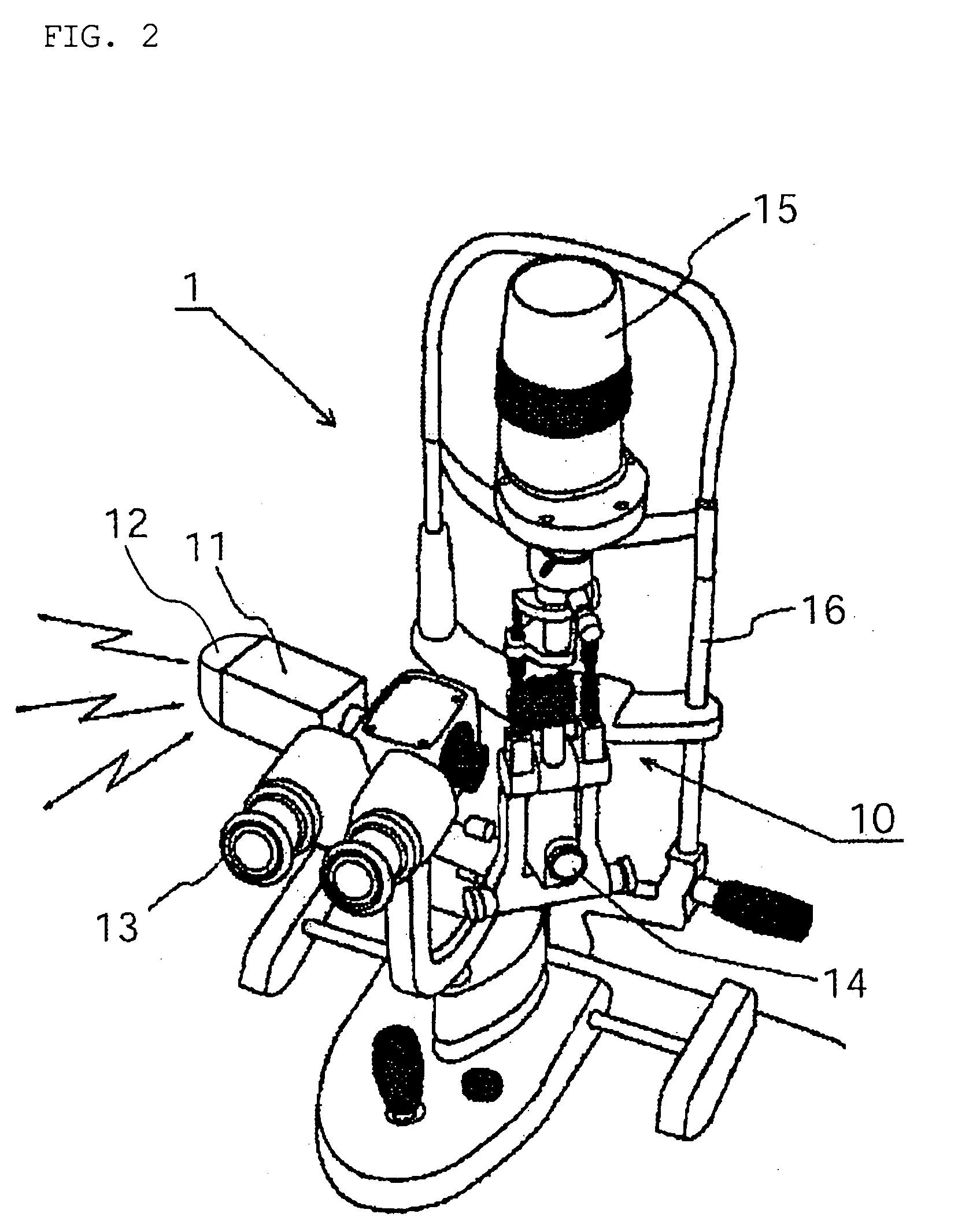
[0028]FIG. 1 illustrates an embodiment of the ophthalmic examination and treatment system in accordance with the present invention. The overall ophthalmic examination and treatment system is represented with reference numeral 1 and comprises various ophthalmic medical instruments (assigned with reference symbols 10, 20, 30, 40) such as a slit lamp 10, an operation microscope 20 or a fundoscopy device, all described hereinbelow, used in ophthalmic diagnosis, imaging devices 11, 21, 31, 41 composed of wireless CCD cameras mounted on the ophthalmic medical instruments 10, 20, 30, 40; and display devices 2 (here, two devices are used) for displaying the images captured with those imaging devices 11, 21, 31, 41.

[0029] In the present embodiment two display devices 2 are used. The reference numeral 5 in the figure stands for a control unit used when manually operating the aforementioned display devices 2 and also the imaging devices 11, 21, 31, 41. The reference numeral 6 stands for a rec...


PUM


Abstract

An object of the present invention is to enable adequate and reliable system management in an ophthalmic examination and treatment system composed of wireless imaging devices mounted on various ophthalmic medical instruments used for ophthalmic examination and treatment and a display device for displaying the images captured by the imaging devices. The ophthalmic examination and treatment system 1 comprises a plurality of ophthalmic medical instruments 10, 20, 30 used in ophthalmic examination and treatment, wireless imaging devices 11, 21, 31 mounted on the respective ophthalmic medical instruments, and at least one display device 2 displaying the images captured with the imaging devices. Each imaging device comprises transmission/reception unit 12, 22, 23 for conducting transmission and reception of information data with the display device by wireless communication. Each transmission/reception unit has an inherent ID allocated correspondingly to each imaging device, transmits a data signal with an ID signal attached thereto to the transmission/reception unit 3 of the display device, and when an ID confirmation signal attached to a control signal from the transmission/reception unit of the display device and the own ID coincide, receives the control signal. The display device receives a data signal with an ID signal attached thereto from each imaging device, conducts displaying with the data signal corresponding to the ID and enables the remote control of the imaging device corresponding to the ID by attaching the ID signal and sending the control signal.

Description

BACKGROUND OF THE INVENTION [0001] 1. Field of the Invention [0002] The present invention relates to a medical instrument, more specifically, an ophthalmic medical instrument to be used in ophthalmic examination and treatment, and particularly to an ophthalmic examination and treatment system equipped with a wireless imaging device and a display device for displaying the captured images thereof. [0003] 2. Description of the Related Art [0004] For example, slit lamps and operation microscopes used in ophthalmic surgery (they are also used in brain surgery) and fundoscopy devices are well known as ophthalmic medical instruments employed during ophthalmic examination and treatment. In those medical instruments, an imaging device is installed permanently or optionally, and this imaging device is used for imaging the condition of the affected area and the state of treatment, and displaying those condition and state on a monitor screen which is a display device provided separately. [0005]...

Claims


Application Information

Patent Timeline
Patent Type & Authority Applications(United States)
IPC IPC(8): A61B3/00A61B3/10
CPCA61B3/0041G06F19/3418A61B3/18A61B3/10G16H40/67
Inventor MAKINO, TOSHIMI
Owner MAKINO OPHTALMIC INSTR
Why Eureka
Try Eureka