Optical element, process for producing the same, substrate for liquid crystal alignment, liquid crystal display device, and birefringent material

a technology of optical elements and liquid crystals, applied in the field of optical elements, can solve the problems of high production cost, high production cost, complex production process, etc., and achieve the effect of low cost and less susceptible to hea

Inactive Publication Date: 2005-09-08
DAI NIPPON PRINTING CO LTD
View PDF13 Cites 22 Cited by
  • Summary
  • Abstract
  • Description
  • Claims
  • Application Information

AI Technical Summary

Benefits of technology

[0051] The birefringent material of the present invention can be produced at low cost and has birefringence characteristics which are less susceptible to heat.

Problems solved by technology

Therefore, the visual angle compensation film described in this literature is disadvantageous in that the production process is complicated and the production cost is high.
For this reason, the production process disclosed in this literature is disadvantageous in that the production cost is sometimes high.
Therefore, the birefringence characteristics are susceptible to heat, and, thus, the temperature range in which desired birefringence characteristics can be maintained is relatively narrow.
This makes it difficult to use the homeotropic alignment-type liquid crystal film, for example, in an on-vehicle liquid crystal display device where relatively high heat resistance is required.
Further, the homeotropic alignment-type liquid crystal film produced by the process described in this literature is disadvantageous in that liquid crystal display devices using the homeotropic alignment-type liquid crystal film can be used only in limited applications.
This results in lowered adhesion to the substrate layer or a significant lowering in birefringence characteristics due to residual stress.
Thus, the homeotropic alignment-type liquid crystal film produced by the process described in Japanese Patent Laid-Open No. 174725 / 2002 is disadvantageous in that the degree of freedom of selection of the member which can form this liquid crystal film is low.
The homeotropic alignment-type liquid crystal film produced by the process described in Japanese Patent Laid-Open No. 121852 / 2003 comprises a side chain-type liquid crystal polymer and thus suffers from the same problem as described above.
Further, in order to provide the homeotropic alignment-type liquid crystal film by the process described in this literature, a binder layer and an anchor layer should be provided in that order on the substrate, and, thus, the production cost is disadvantageously increased.

Method used


Image

  • Optical element, process for producing the same, substrate for liquid crystal alignment, liquid crystal display device, and birefringent material
  • Optical element, process for producing the same, substrate for liquid crystal alignment, liquid crystal display device, and birefringent material
  • Optical element, process for producing the same, substrate for liquid crystal alignment, liquid crystal display device, and birefringent material

Examples


first embodiment of

(a) First Embodiment of Production Process of Optical Element

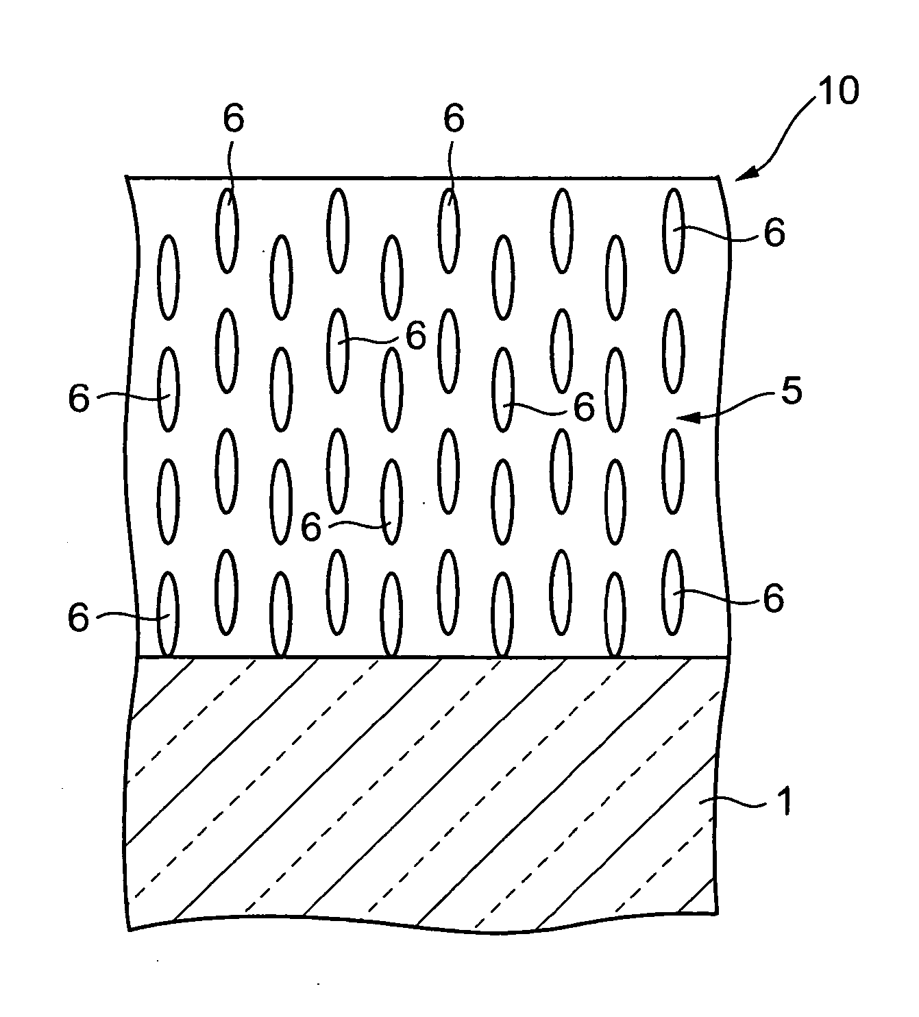
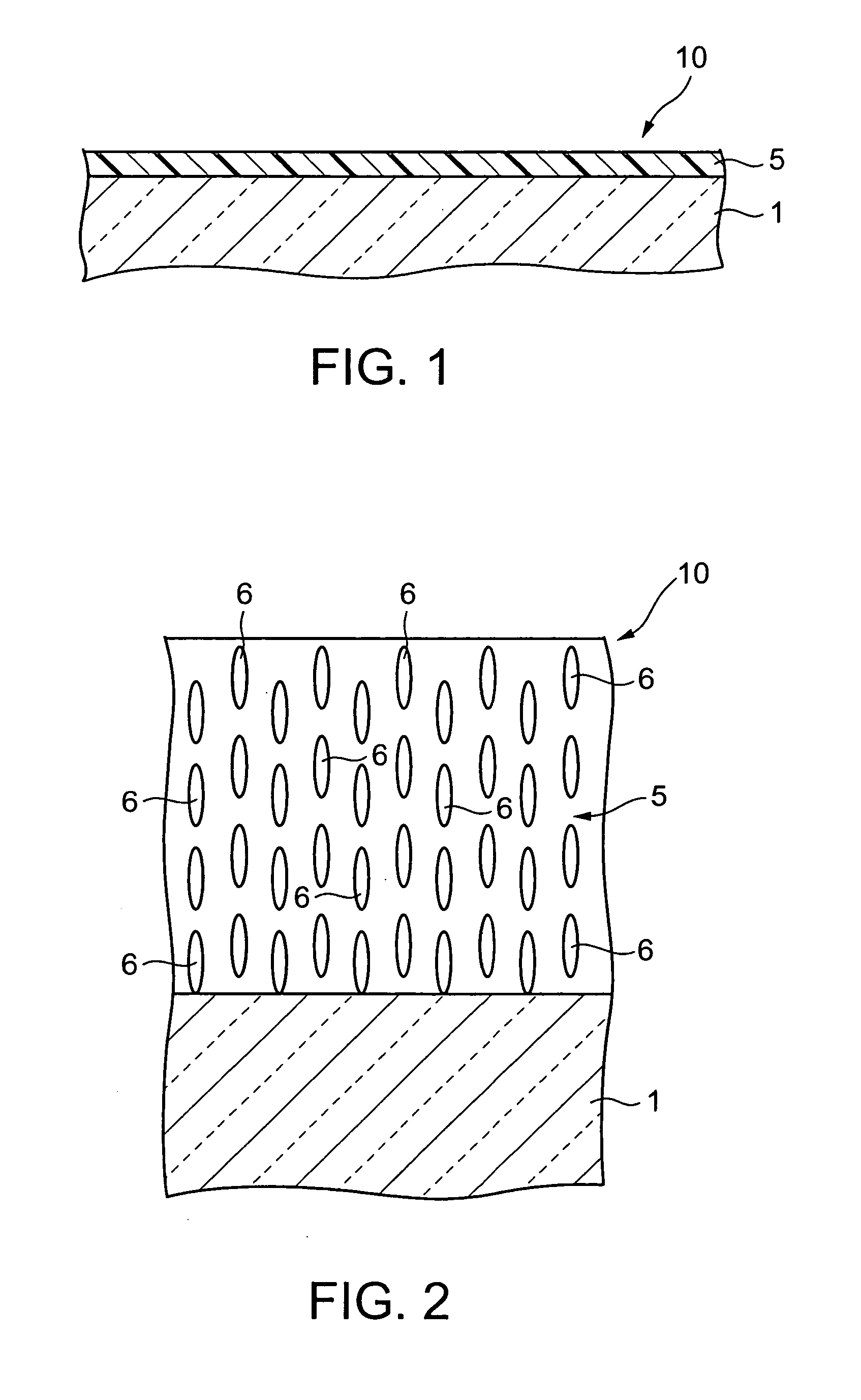
[0252] The production process of the optical element according to the present invention is a production process of an optical element comprising a substrate and a first birefringence layer provided on the substrate and comprises a coating step, an alignment step, and a crosslinking step.

(1) Coating Step

[0253] In the coating step, a coating of a coating composition containing at least a polymerizable liquid crystal comprising rodlike molecules each having two or more polymerizable functional groups is formed on the substrate.

[0254] The substrate and the coating composition may be the same as those used in the production process of the optical element in the first embodiment.

(2) Alignment Step

[0255] In the alignment step, the polymerizable liquid crystal in the coating formed in the coating step is aligned in a homeotropic form. In this case, the coating is heated to a temperature at which the polymerizable liquid cry...

second embodiment of

(b) Second Embodiment of Production Process of Optical Element

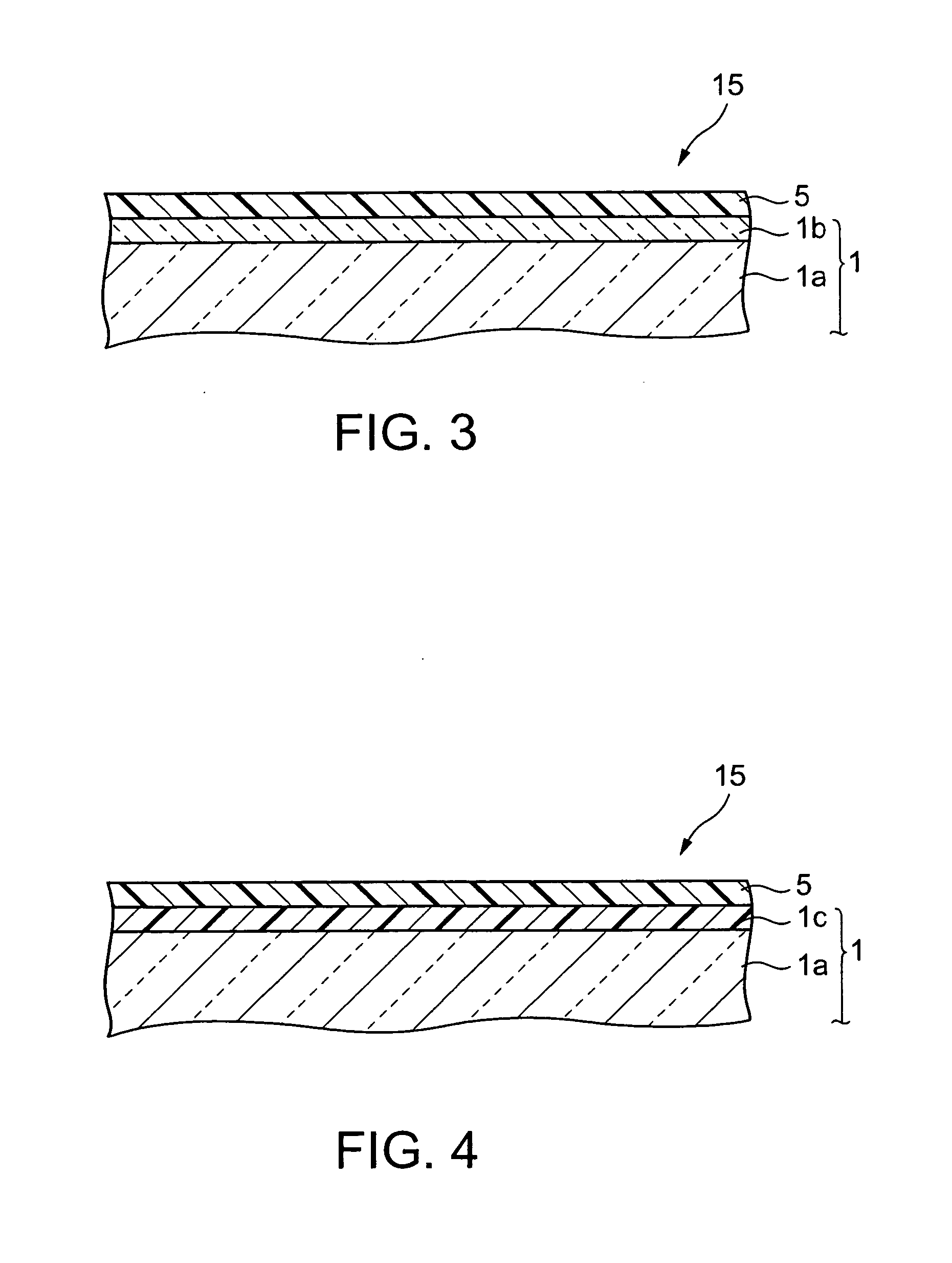
[0283] In the production process of the optical element in this embodiment, a substrate having a vertically aligning film, which can align, in a homeotropic form, the polymerizable liquid crystal comprising rodlike molecules, is used, and a coating is formed on the vertically aligning film by the coating step.

[0284] The vertically aligning film may be the same as that described above in connection with the optical element according to the present invention. In the production process of an optical element in this embodiment, the optical element is produced by successively conducting a coating step, an aligning step, and a crosslinking step in the same manner as in the production process in the first embodiment, except that the substrate has the above vertically aligning film.

[0285] As schematically shown in FIG. 25, in the optical element 130 thus obtained, a light transparent substrate 101 and a vertically aligning film...

third embodiment of

(c) Third Embodiment of Production Process of Optical Element

[0288] In the production process of the optical element in this embodiment, a polymerizable liquid crystal comprising rodlike molecules and a surfactant, which can cause homeotropic alignment are incorporated in the coating composition used in the coating step. The polymerizable liquid crystal and the surfactant have been described above in connection with the optical element according to the present invention, and, thus, the description thereof will be omitted.

[0289] In the production process of the optical element in this embodiment, an optical element is produced by successively conducting a coating step, an aligning step, and a crosslinking step in the same manner as in the production process of the first embodiment or the second embodiment, except that the surfactant is incorporated in the coating composition used in the coating step.

[0290] In forming the first birefringence layer, the polymerizable liquid crystal c...


PUM


Abstract

There are provided an optical element, which can be produced at low cost and has birefringent characteristics with low susceptibility to heat, and a process for producing the same. The optical element comprises: a light transparent substrate; and a first birefringence layer provided on the substrate, wherein the first birefringence layer comprises a crosslinked polymer comprising a coupling agent and/or a surfactant which can homeotropically align a polymerizable liquid crystal comprising rodlike molecules; and the crosslinked polymer has a three-dimensionally crosslinked structure in such a state that the polymerizable liquid crystal comprising rodlike molecules holds homeotropic alignment.

Description

BACKGROUND OF THE INVENTION [0001] 1. Field of the Invention [0002] The present invention relates to an optical element comprising a birefringence layer and a process for producing the same, a substrate for liquid crystal alignment having a birefringence layer, and a liquid crystal display device comprising the substrate for liquid crystal alignment. The present invention also relates to a birefringent material. [0003] 2. Background Art [0004] Liquid crystal display devices have advantages including that a reduction in thickness and a reduction in weight can be easily realized, the power consumption is low, and the occurrence of flicker can easily be prevented. By virtue of these advantages, liquid crystal display devices have drawn attention as flat panel displays, and the market of liquid crystal display devices for use as display devices of personal computers or television receivers have been rapidly expanded. Further, an increase in size of the liquid crystal display device is a...

Claims


Application Information

Patent Timeline
Patent Type & Authority Applications(United States)
IPC IPC(8): G02B5/30
CPCG02F1/133514G02F1/13363G02F2001/133567G02F2001/133633Y10T428/10G02F2202/022G02F2413/03Y10T428/1014Y10T428/1036G02F2001/133638C09K2323/00C09K2323/023C09K2323/03G02F1/133567G02F1/133633G02F1/133638
Inventor ISHIZAKI, KOJIIKEGAMI, KANAMI
Owner DAI NIPPON PRINTING CO LTD
Why Eureka
Try Eureka