Bearing vibration measuring apparatus, bearing vibration measuring method, and radial type bearing

a technology of bearing vibration and measuring equipment, applied in mechanical equipment, instruments, static/dynamic balance measurement, etc., can solve the problems of inability to apply the correct thrust load and high price of the apparatus

Active Publication Date: 2005-09-08
NSK LTD
View PDF2 Cites 11 Cited by
  • Summary
  • Abstract
  • Description
  • Claims
  • Application Information

AI Technical Summary

Benefits of technology

[0009] The invention has been carried out in view of the above-described situation and it is an object thereof to provide a small-sized and inexpensive bearing vibration measuring apparatus and an inexpensive bearing vibration measuring method capable of measuring a flaw or an inclusion by providing an arbitrary inclination to an inner ring or an outer ring, capabl

Problems solved by technology

However, in the above-described bearing vibration measuring apparatus 70, the press rotating unit 79 for making the pressing jig 80 carry out the precession movement is provided with a complicated struc

Method used


Image

  • Bearing vibration measuring apparatus, bearing vibration measuring method, and radial type bearing
  • Bearing vibration measuring apparatus, bearing vibration measuring method, and radial type bearing
  • Bearing vibration measuring apparatus, bearing vibration measuring method, and radial type bearing

Examples


first embodiment

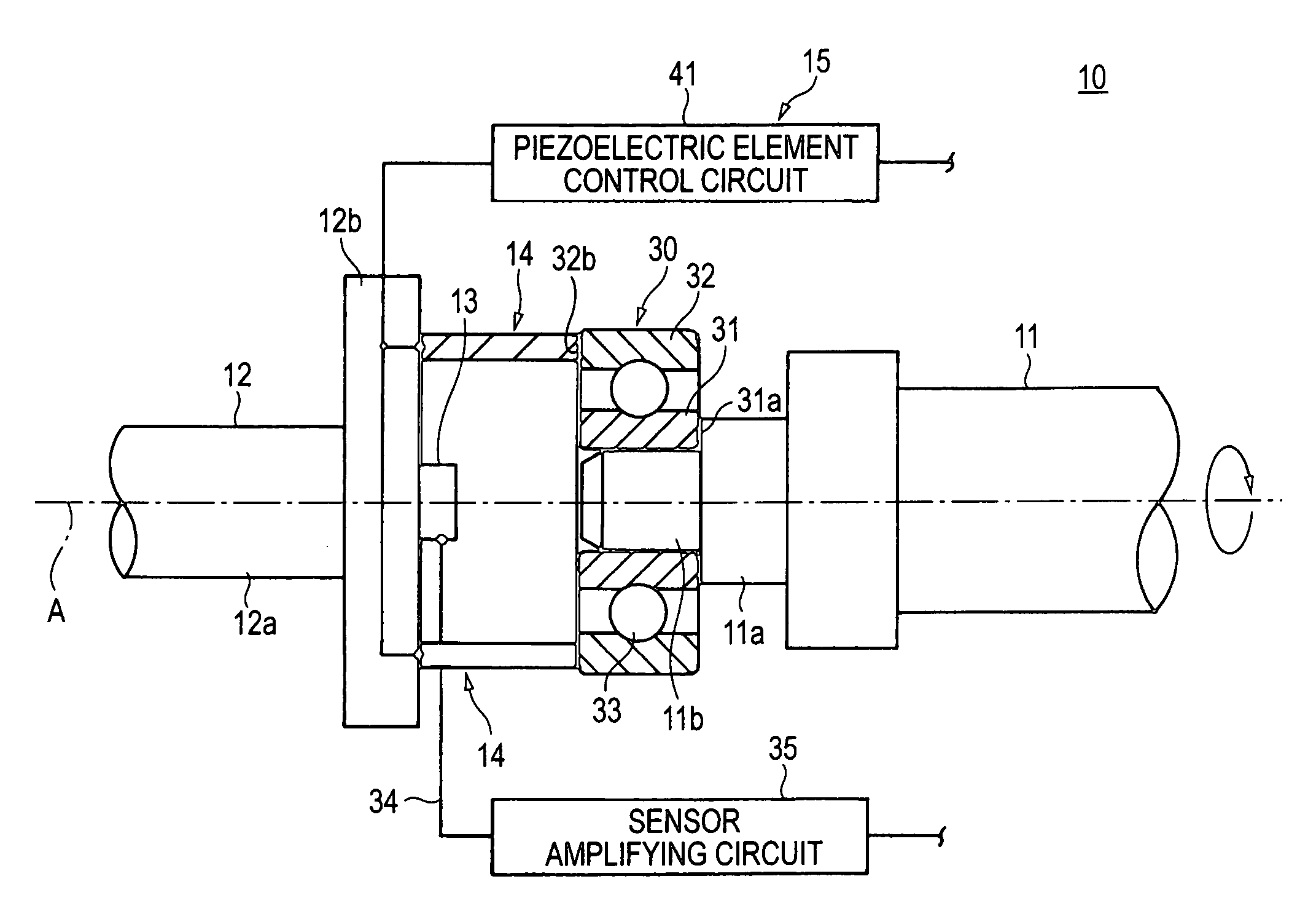
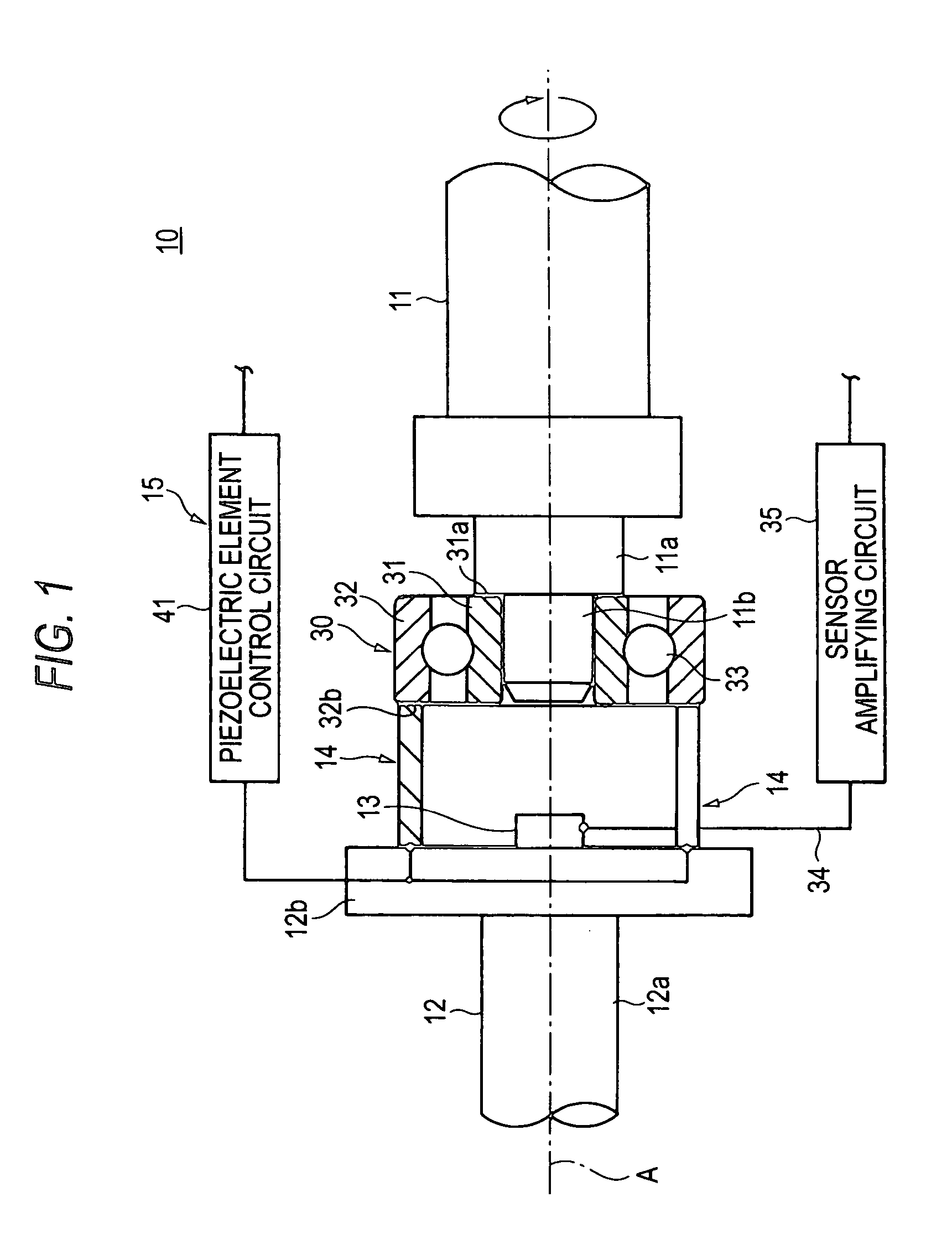
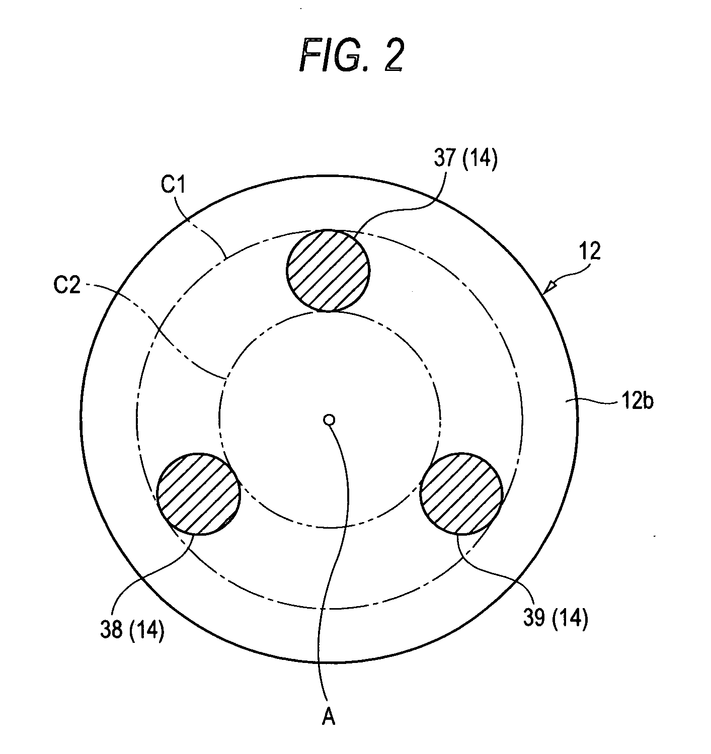
[0039]FIG. 1 is a schematic view showing a first embodiment of a bearing vibration measuring apparatus according to the invention, FIG. 2 is a view for explaining an arrangement of a piezoelectric element used as a mechanism of driving the bearing vibration measuring apparatus shown in FIG. 1, FIG. 3 is a block diagram of a control circuit used in the bearing vibration measuring apparatus shown in FIG. 1, FIG. 4 is a timing chart for explaining a control of driving the piezoelectric element by the control circuit shown in FIG. 3, and FIG. 5 is a diagram showing an example of a waveform of detecting a flaw detected by the bearing vibration measuring apparatus shown in FIG. 1, particularly a waveform when vibration of a bearing having a flaw at a vicinity of a shoulder of an outer ring is measured.

[0040] As shown by FIG. 1, a bearing vibration measuring apparatus 10 constituting the first embodiment of the invention is an apparatus of measuring vibration of a bearing 30 and is provid...

second embodiment

[0061]FIG. 6 is a schematic view showing a second embodiment of a bearing vibration measuring apparatus according to the invention. Further, in the following explanation, an explanation will be simplified or omitted with regard to members or the like having constitution and operation similar to those of members or the like of the bearing vibration measuring apparatus 10 which has already been explained by attaching the same notations or corresponding notations in the drawings.

[0062] A bearing vibration measuring apparatus 50 constituting the second embodiment of the invention is an apparatus of measuring vibration of the bearing 30 as shown by FIG. 6 and the apparatus includes a spindle arbor 51 formed with an outer ring fitting portion 51a outwardly fitted to the outer ring 32 of the bearing 20 and brought into contact with one end face 32a of the outer ring 32 and the driving mechanism 14 including three pieces of the first, the second and the third piezoelectric elements 37, 38 ...


PUM


Abstract

A bearing vibration measuring apparatus is an apparatus of measuring vibration of a bearing. The bearing vibration measuring apparatus detects a vibration component generated from the bearing in a state of pressing one of an inner ring and an outer ring of the bearing in an axial direction while relatively rotating other of the inner ring and the outer ring to detect a defect of the bearing based on the vibration component. The bearing vibration measuring apparatus includes a driving mechanism elongated and contracted for inclining the inner ring or the outer ring.

Description

BACKGROUND OF THE INVENTION [0001] 1. Field of the Invention [0002] The prevent invention relates to a bearing vibration measuring apparatus and a bearing vibration measuring method for detecting a defect of a bearing based on vibration generated from the bearing and a radial type bearing vibration of which is measured by a bearing vibration measuring apparatus. [0003] 2. Description of the Related Art [0004] There is known a bearing vibration measuring apparatus 70 shown in FIG. 12 as an example of a bearing vibration measuring apparatus of a related art (refer to, for example, JP-A-2002-350289 (pages 2 through 4, FIG. 1)). [0005] In the bearing vibration measuring apparatus 70, a straight arbor 73 is fitted to an inner ring 72 of a bearing 71, and the straight arbor 73 is connected to a rotating main spindle of a motor 74. The motor 74 is supplied with an alternating current power from an inverter 75 and is rotated at a resolution number in accordance with a frequency of the alter...

Claims


Application Information

Patent Timeline
IPC IPC(8): G01M13/04F16C19/04G01H11/08G01H17/00G01M7/02
CPCF16C19/527G01M13/045G01H1/003F16C2233/00
Inventor MAEDA, TAKASHINAKAJIMA, KAZUMASAKAWAMATA, TAKEO
Owner NSK LTD
Why Eureka
Try Eureka