Integrated loop resonator with adjustable couplings and methods of using the same

a loop resonator and coupling technology, applied in the field of integrated optical devices, can solve the problems of difficult to ensure the matching of the two coupling gaps/lengths on the two sides of the resonator cavity, the inability to easily tune the coupling coefficient, and the inability to achieve the finesse and the extinction ratio of the resonator

Inactive Publication Date: 2005-09-08
CELIGHT
View PDF3 Cites 42 Cited by
  • Summary
  • Abstract
  • Description
  • Claims
  • Application Information

AI Technical Summary

Benefits of technology

[0017] Accordingly, an object of the present invention is to provide devices, and their methods of use, for real time compensation of losses and changes in the integrated optical devices with loop resonator structures and optimization of their output / performance.

Problems solved by technology

Because of the high optical confinement and short coupling distances, the coupling coefficients are not readily tuned once the device is fabricated, especially in an independent fashion.
In particular, it is difficult to ensure that the two coupling gaps / lengths on two sides of the resonator cavity are matched.
The finesse and the extinction ratio of the resonator would be impaired if the coupling factors and resonator phase are not matched for desirable conditions.
In general, while providing the high-density integration potential, small dimensions make efficient adjustments of cavity parameters a challenging task, limiting their direct implication within various optical systems.
The speed and accuracy of thermal tuning, however, are not sufficient for high-speed applications.
Reported methods for adjustable coupling are limited to single coupler tuning by using thermal or electro-optical perturbations of the refractive index, which is inseparable with the cavity phase change.
None of the above described prior art technologies proposed a separate adjustment of coupling ratios of the input and output waveguides coupled to a loop resonator with losses.
This fact limits boundaries of loop resonator structures not allowing dynamic, such as real time, optimization of resonator output / performance.
In addition, lack of mentioned resonators tunability disables an effective compensation of fabrication errors and / or changes in environmental conditions, thus decreasing the manufacturing yield and productivity.

Method used


Image

  • Integrated loop resonator with adjustable couplings and methods of using the same
  • Integrated loop resonator with adjustable couplings and methods of using the same
  • Integrated loop resonator with adjustable couplings and methods of using the same

Examples


example 1

[0075] An Optical Frequency Comb Generator (OFCG) can be realized in one embodiment of the invention. OFCG consists of a central optical frequency carrier having a set of equally spaced sidebands on either side. The sidebands must be equally spaced if the optical frequency comb is to be phase coherent. The spacing between the sidebands is determined by the frequency of the RF or microwave signal that modulates the optical carrier.

[0076] The phase modulation sidebands must be resonant with the optical cavity modes, hence the term resonant electro-optic modulation, and this condition is met if the modulation frequency is equal to an integer multiple of the optical cavity free spectral range (FSR). Therefore the modulation frequency is in the microwave domain, and the highest practical modulation frequency (10 GHz to 30 GHz) is used because one wishes to achieve the largest OFCG span with the least number of sidebands to reduce the noise. The intensity of the sidebands is determined b...

example 2

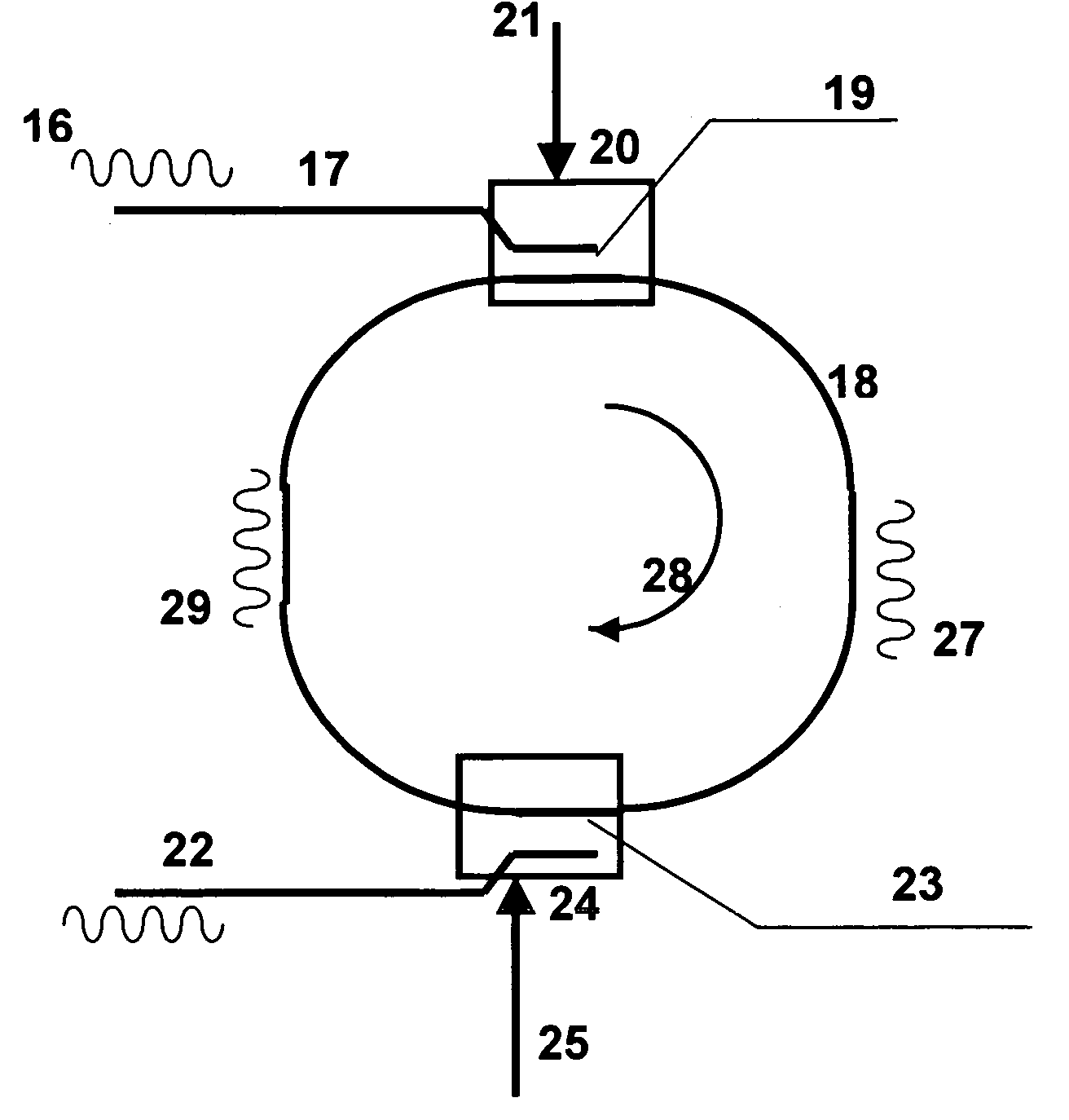
[0079] The improvement in the selective diffusion of Er ions has resulted in new integrated devices based on optical amplification. A great deal of effort has been made in realizing optically pumped Er-doped LiNbO lasers, see for example “Advanced Ti:Er:LiNbO3 Waveguide Lasers”, by C. Becker et al. in IEEE J. Selected Topics Quantum Electron., vol. 6, No.1 pp. 101-113, September 2000. Incorporation of a gain element in the resonant loop 18 of the disclosed integrated device allows creating of an efficient narrowband laser with adjustable characteristics. A two-coupler-type Er-doped-fiber ring resonator can compensates for the round-trip optical loss by optical amplification thereby attaining a high finesse. Their performance can be flexibly tailored and the quality factor is adjustable by the tuning of couplings 19 and 23 along with the trimming of the gain of the optical amplifier.

[0080]FIG. 14 depicts the basic scheme for laser beam generation using the loop resonator integrated ...

example 3

[0082] Efficient high-speed electro-optic amplitude modulators can be realized using the disclosed invention. External modulators have proved more challenging with respect to power efficiency and high frequency. Currently, the most efficient modulators demonstrated in the laboratory are of the traveling wave type, and require half-wave voltages (Vpi) in excess of several volts while generally limited to frequencies about 50 GHz. The use of ring resonators as modulators can have substantial, orders of magnitude, improvement in efficiency and result in significant impact on the-technology of optical information generation and transfer, in commercial and specialized government systems.

[0083] Proposed invention enables further improvement of the voltage efficiency of the external modulation while extending the frequency of modulation to above 100 GHz, in a small device. Thus extinction ratio and Vpi, can be adjusted by tuning of resonator couplers ratios K1 and K2 along with phase-shif...


PUM


Abstract

An integrated optical device with a loop resonator is provided, having at least one closed waveguiding loop which has losses. A coupler and at least one input waveguide is coupled to the loop resonator, An adjustment unit controls a coupling coefficient K1 of the coupler, and a second coupler is coupled to the loop resonator. At least one output waveguide is coupled with the second coupler to the loop resonator. Another adjustment unit is configured to control coupling coefficient K2 of the second coupler, being related to the value of K1, accordingly to the following equation K2=f{K1,ξ}, providing Q{K2}=Max{Q}, where (1−ξ) are the total optical losses within the loop resonator and Q is a resonator characteristic.

Description

[0001] The present invention claims the benefit of U.S. Provisional patent application Ser. No. 60 / 451,250, filed Feb. 27, 2004 and U.S. Provisional patent application Ser. No. 60 / 549,428 filed Oct. 28, 2004.FIELD OF INVENTION [0002] The present invention relates generally to the integrated optical devices, and their methods of use, that have waveguide loop (ring) resonators, and more particularly to integrated optical devices, and their methods of use, that have adjustable characteristics and are useful for modulating, wavelength filtering, routing, light modulation, switching, lasing, multiplexing / demultiplexing, frequency comb generation and sensing BACKGROUND [0003] In the expanding integrated optical technology, a number of discrete structures have been proposed to serve as optical building blocks for controlling optical signals of specific wavelengths. Such structures include devices with circular, ring, disc, or sphere shaped active or passive cavities, which are useful compo...

Claims


Application Information

Patent Timeline
Patent Type & Authority Applications(United States)
IPC IPC(8): G02B6/26
CPCG02B6/12007H01S3/083H01S3/0632G02F1/3132G02F2203/15
Inventor KAPLAN, ARKADY
Owner CELIGHT
Why Eureka
Try Eureka