Vacuum pumping system, driving method thereof, apparatus having the same, and method of transferring substrate using the same

a vacuum pumping system and driving method technology, applied in the direction of static indicating devices, machines/engines, transportation and packaging, etc., can solve the problems of large footprint of the cluster, high cluster cost, and damage to the substrate and components of the apparatus, so as to reduce the footprint, reduce the cost of the apparatus, and efficiently utilize the apparatus

Inactive Publication Date: 2005-09-08
JUSUNG ENG
View PDF15 Cites 23 Cited by
  • Summary
  • Abstract
  • Description
  • Claims
  • Application Information

AI Technical Summary

Benefits of technology

[0038] An object of the present invention is to provide an apparatus of manufacturing a substrate for a semiconductor device and a liquid crystal display device that efficiently utilizes the apparatus by reducing a footprint and decreases costs for the apparatus.
[0039] Another object of the present invention is to provide a vacuum pumping system and a pumping method using the same that increase a pumping speed of a process apparatus.
[0040] Another object of the present invention is to provide a venting system and a venting method using the same that minimize temperature variation and thermal impacts inside a chamber increasing a venting speed.

Problems solved by technology

This causes a large footprint of the cluster and high costs of the cluster due to the transfer chamber 70 and the transfer chamber robot 12.
If the pumping speed is fast at an early stage of pumping, the substrate and components of the apparatus may be damaged.
However, because the vacuum pumping system has a slow pumping speed, it is difficult to frequently use the vacuum pumping system, and the vacuum pumping system is widely used in a step for setting an apparatus.
If gases flow into the chamber in quantity to reduce the venting time, it is impossible to uniformly maintain the inner temperature of the chamber, and thus reproductivity of the processes is reduced.
In addition, since degradation of the apparatus and generation of particles may be caused due to thermal impacts, there is limitation on periodically venting the process chamber during the processes.

Method used


Image

  • Vacuum pumping system, driving method thereof, apparatus having the same, and method of transferring substrate using the same
  • Vacuum pumping system, driving method thereof, apparatus having the same, and method of transferring substrate using the same
  • Vacuum pumping system, driving method thereof, apparatus having the same, and method of transferring substrate using the same

Examples


Embodiment Construction

[0062] Reference will now be made in detail to the preferred embodiments, examples of which are illustrated in the accompanying drawings.

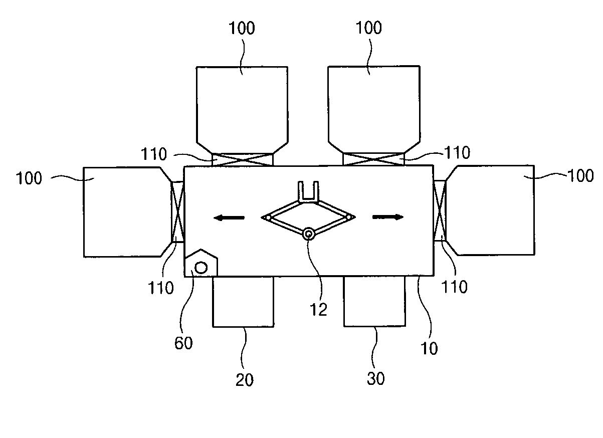
[0063]FIGS. 4A to 4E are views schematically showing examples of a process apparatus according to the present invention. As shown in the figures, the apparatus includes a transfer unit 10, a plurality of process chambers 100, and first and second load ports 20 and 30. The transfer unit 10 is under an atmospheric condition and has a robot 12 therein. The process chambers 100 and the first and second load ports 20 and 30 are connected to sides of the transfer unit 10. The number of the process chambers 80 and the number of the load ports 20 and 30 may be changed.

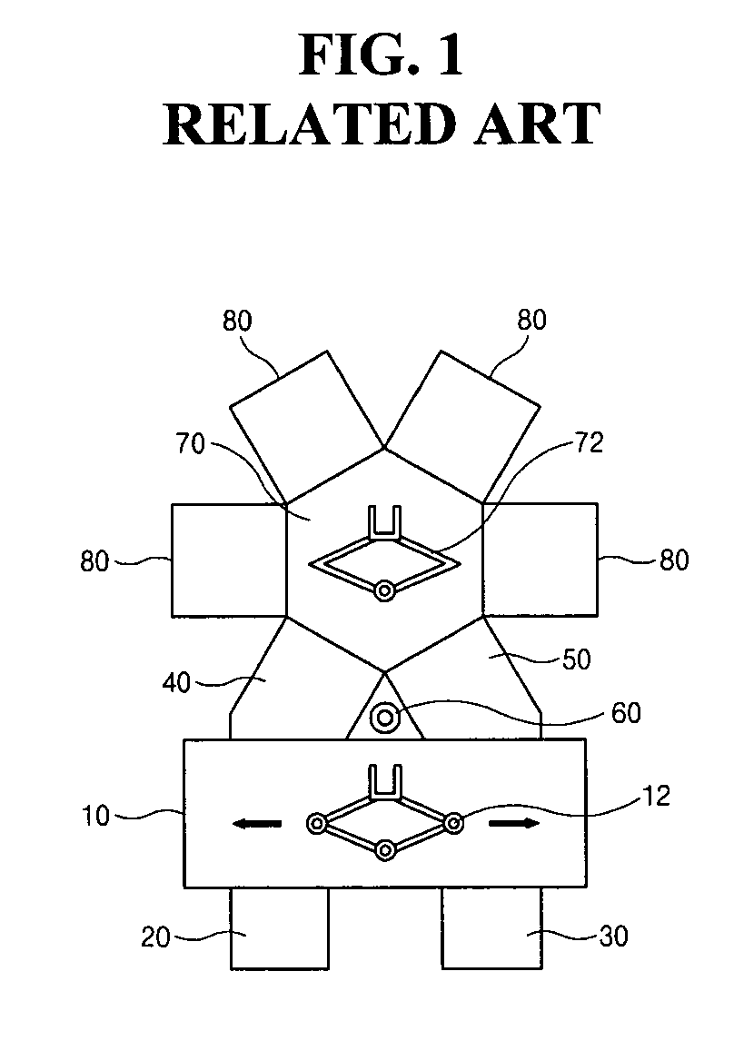
[0064] The apparatus excludes a transfer chamber, a transfer chamber robot and load-lock chambers 40 and 50 as compared to the apparatus of the related art of FIG. 1. In the present invention, the transfer unit 10 further acts as the related art transfer chamber 70, and the process chambers...


PUM

PropertyMeasurementUnit
pressureaaaaaaaaaa
pressureaaaaaaaaaa
pressureaaaaaaaaaa

Abstract

An apparatus includes a transfer unit under an atmospheric condition and having a robot therein; and at least one process chamber connected to one side of the transfer unit with a slot valve there between, and being alternately under a vacuum condition and under an atmospheric condition.

Description

[0001] The present invention claims the benefit of Korean Patent Applications No. 2004-0015544 filed on Mar. 8, 2004, No. 2004-0017627 filed on Mar. 16, 2004, No. 2004-0017832 filed on Mar. 17, 2004, and No. 2005-0014819 filed on Feb. 23, 2005, which are hereby incorporated by references. BACKGROUND OF THE INVENTION [0002] 1. Field of the Invention [0003] The present invention relates to a vacuum pumping system, a driving method thereof, an apparatus having the same, and a method of transferring a substrate using the same. [0004] 2. Discussion of the Related Art [0005] In general, a semiconductor device or a liquid crystal display (LCD) device is fabricated by repeating a deposition step of a thin film on a substrate, a photolithographic step using a photoresist, a selective etch step of the thin film and a cleaning step of the substrate several times or several ten times. These steps for a fabrication process of a semiconductor device or an LCD device may be performed using an appa...

Claims


Application Information

Patent Timeline
Patent Type & Authority Applications(United States)
IPC IPC(8): B65G1/00C23C16/00F04D17/10G02F1/133H01L21/00
CPCH01L21/67017H01L21/67173H01L21/67167H01L21/67161Y10T137/86083Y10T137/86139
Inventor KIM, HONG-SEUBPARK, HYUN-SOOJUNG, SOON-BINCHA, SUNG-HOKIM, DONG-JINHWANG, WOOK-JUNGYOO, JIN-HYUK
Owner JUSUNG ENG
Why Eureka
Try Eureka