HPLC column design and method of making same

a technology of liquid chromatography and column length, applied in the field of high-performance liquid chromatography technology, can solve the problems of increasing costs of thread machining, affecting the uniformity of temperature along the column length, and affecting the quality of hplc columns, so as to achieve economic and easy fabrication

Active Publication Date: 2005-09-15
S T E I C TECH
View PDF22 Cites 19 Cited by
  • Summary
  • Abstract
  • Description
  • Claims
  • Application Information

AI Technical Summary

Benefits of technology

[0010] A basic object of this invention is to provide an improved HPLC column defined by a column tube and couplings held relative to the column tube ends, where the maximum exterior radial column surfaces will be the column tube, not the end couplings, and can be uniformly cylindrical substantially end to end for economical and easy fabrication and labeling even the short 10 mm columns.

Problems solved by technology

However, thread machining adds costs, as does machining needed to form the multi-faced fittings (hex shapes or the like) for defining faces to accept a wrench or other tool for tightening the threaded components together.
Several problems can occur with separation columns having the above noted end couplings.
However, as the end couplings project radially beyond the tube exterior, only they contact the thermal plate (while the column mid-section is gapped from the thermal plate), meaning temperature uniformity along the column length remains uncertain.

Method used


Image

  • HPLC column design and method of making same
  • HPLC column design and method of making same
  • HPLC column design and method of making same

Examples


Embodiment Construction

[0020] In describing this invention, the structural needs of the identified components to be noted herein are well known to those common to the industry. For example, the tubes and end couplings conventionally might be of stainless steel; the filter might be of mesh or a sintered material having micro-sized particles, such as stainless steel, titanium, or a durable plastic such as poly-ether-ether-keton (PEEK); and the resilient sealing structure might also be of a durable plastic or PEEK.

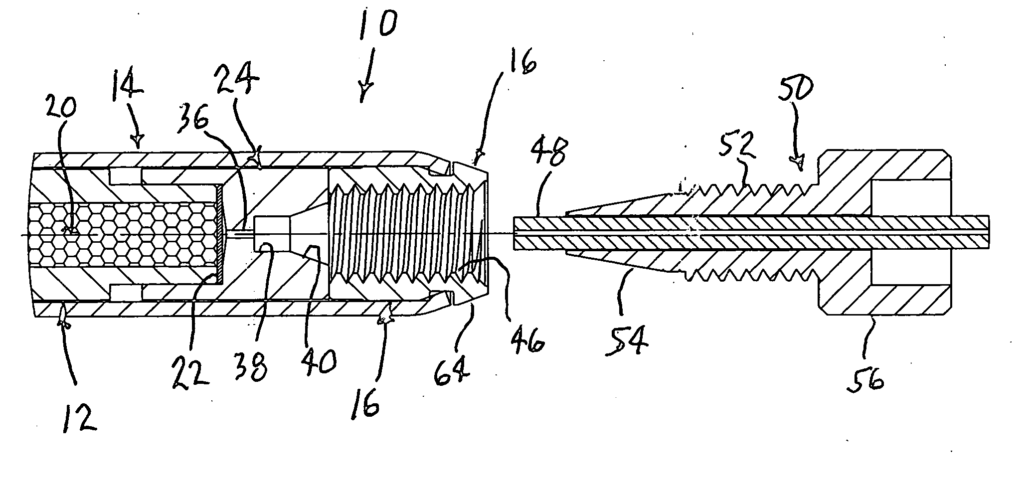
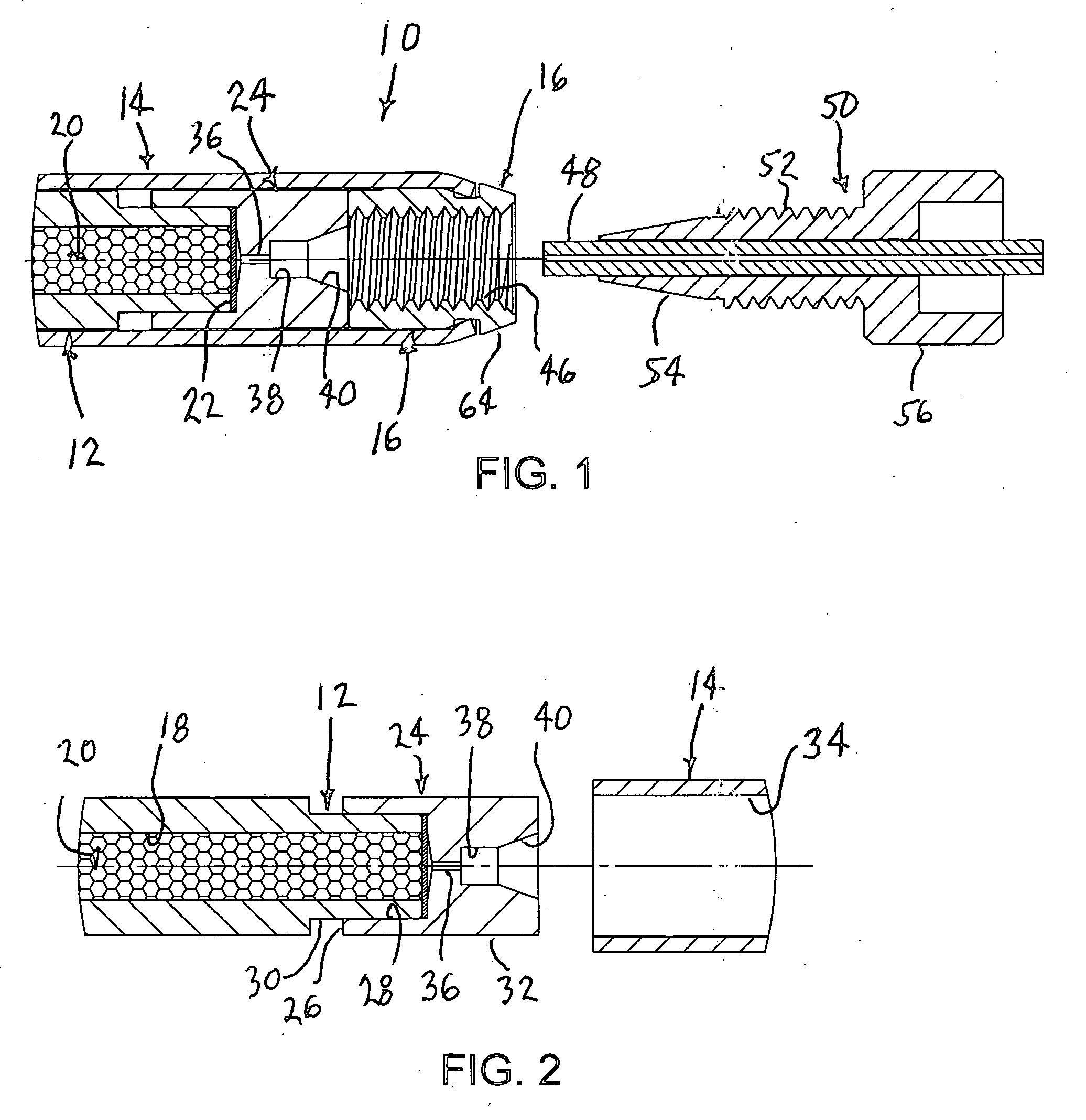
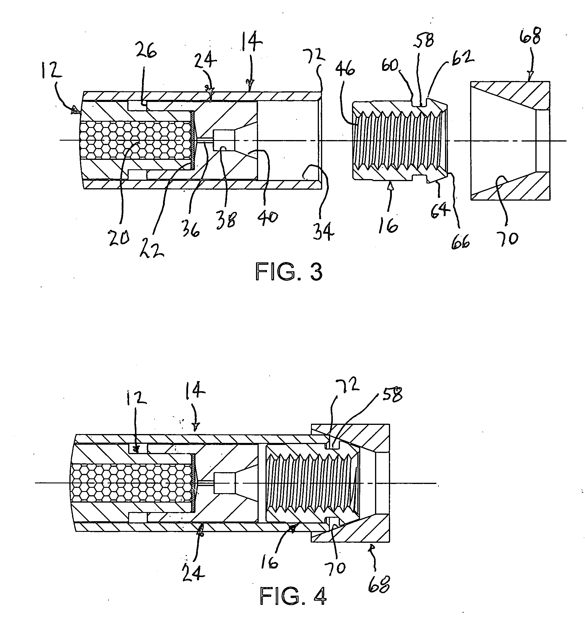
[0021] The improved HPLC column 10 is comprised of an inner tube 12 and an outer tube 14 telescoped together, and end couplings 16 sealed adjacent or secured relative to the ends of the tubes.

[0022] The inner tube 12 has a through bore 18 of uniform diameter from end to end with highly polished or finished inner surfaces. An absorbent 20 of micro-sized particles is densely packed in this bore 18. A mesh or sintered filter 22 is located crosswise to the bore 18, for substantially closing its open ...


PUM


Abstract

The disclosed HPLC column is formed with overlying concentric inner and outer tubes. The flow path is established via the inner tube bore that holds packed absorbent, end filters and capping sealing members, and end coupling members cooperate with the inner tube at its ends. The sealing and end coupling members have conventional configurations for establishing a sealed connection with capillary lines and their fittings, for the series flow testing use through the column. The inventive method and manner of assembly provides that the outer tube overlies all of the inner tube and both sealing members, but only part of each end coupling member. The ends of the outer tube are then deformed radially inward to become mechanically interlocked with the end coupling members, as the column, holding also the filters and sealing members within the inner tube.

Description

FIELD OF THE INVENTION [0001] This invention relates to the high performance liquid chromatography technology (herein referred to as HPLC), and more specifically to the separation column(s) used therein. BACKGROUND OF THE INVENTION [0002] HPLC technology is widely used to detect and identify different components contained in a test sample or specimen material. A typical HPLC instrument has a high pressure pump for forcing a suitable solvent, via capillary lines, at a constant flow rate serially through a sampler, a separation column and a UV or other type detector. Periodically, a small quantity of the test sample will be injected via the sampler into this flowing solvent stream to travel then somewhat as a slug with the solvent stream into the separation column. The separation column contains an absorbent reactive anticipated sub phase components in the test sample. Thus, the different sub phases pass through the detector at different rates, producing separated flow through the det...

Claims


Application Information

Patent Timeline
Patent Type & Authority Applications(United States)
IPC IPC(8): B01D15/08
CPCG01N30/6039
Inventor ZELECHONOK, YURYALKHOVSKY, MIKHAILORLOVSKY, VLADISLAV
Owner S T E I C TECH
Why Eureka
Try Eureka