Method of assembling a fuel injector

a fuel injector and assembly method technology, applied in the direction of generators/motors, mechanical equipment, machines/engines, etc., can solve the problems of unsatisfactory arrangement and adversely affect the performance of the fuel injector, and achieve the effect of softening the volume of sealing materials

Inactive Publication Date: 2005-09-15
DELPHI TECH INC
View PDF7 Cites 9 Cited by
  • Summary
  • Abstract
  • Description
  • Claims
  • Application Information

AI Technical Summary

Benefits of technology

[0007] According to a first aspect of the present invention there is provided a method of assembling a fuel injector comprising a fuel injector body having an accumulator volume defined therein, the method comprising: providing an encapsulated actuator arrangement having a piezoelectric actuator stack and electrical connector means, wherein the stack is encapsulated in a sleeve member; providing a volume of sealing material in the region of the electrical connector means; locating the encapsulated actuator arrangement in the accumulator volume; applying heat indirectly to the volume of sealing material so as to soften the volume of sealing material; and applying pressure to the encapsulated actuator arrangement such that the volume of sealing material deforms to form a substantially fluid-tight seal between the encapsulated actuator arrangement and the accumulator volume in the region of the electrical connector means.

Problems solved by technology

Any such leakage of fuel will of course affect the integrity of the electrical connection and thus adversely affect the performance of the fuel injector.
This arrangement is not ideal, as it does not take into account variations in the sizes of components which occur during the manufacture thereof.

Method used


Image

  • Method of assembling a fuel injector
  • Method of assembling a fuel injector
  • Method of assembling a fuel injector

Examples


first embodiment

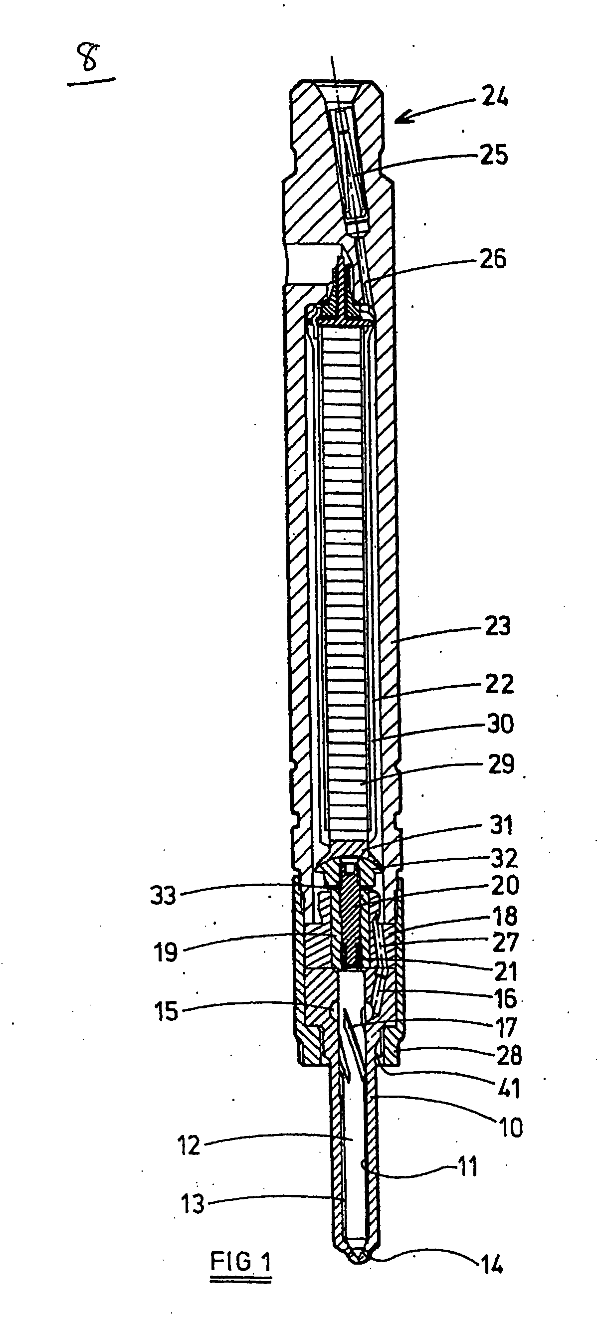
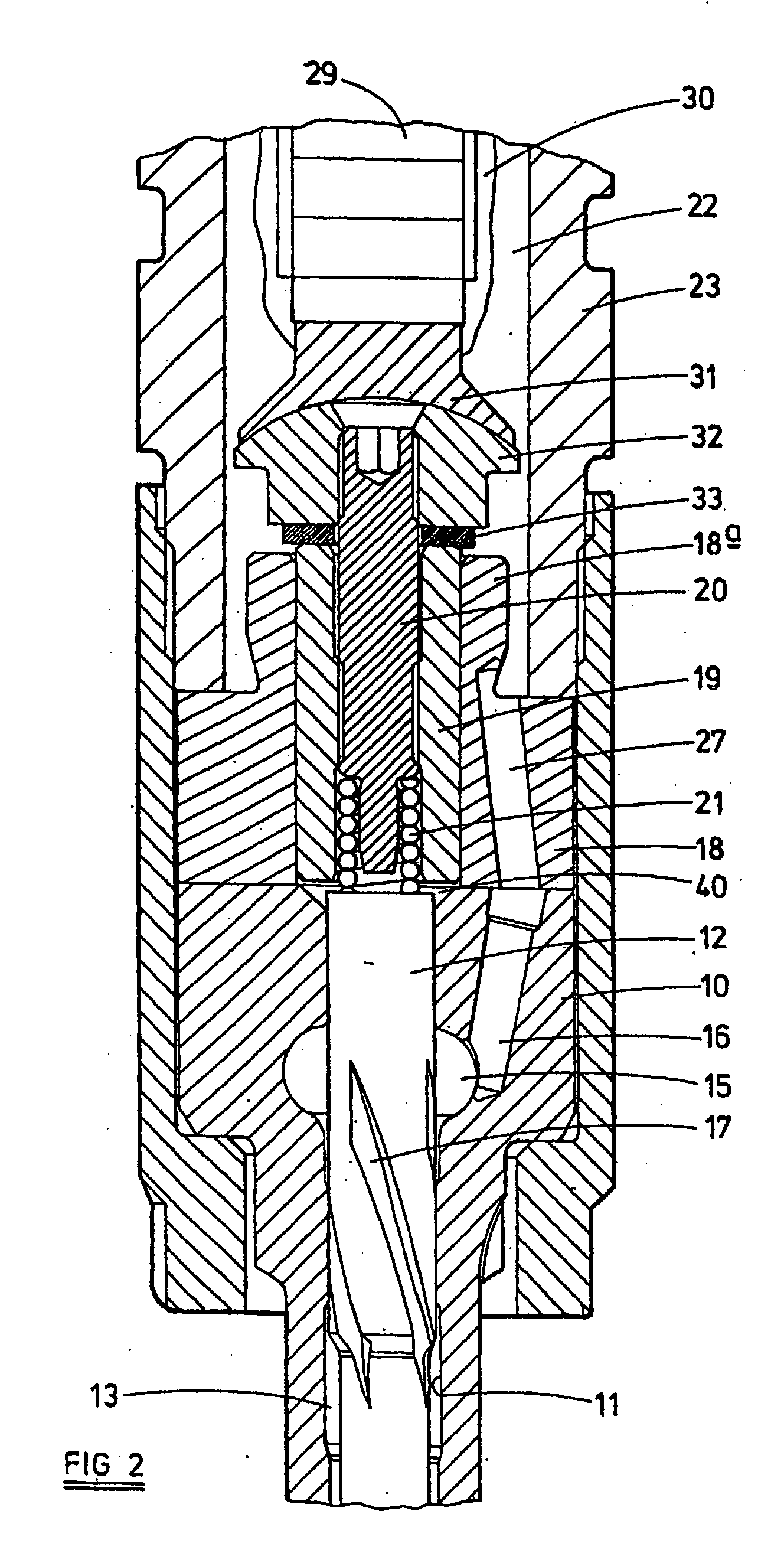
[0038] A method of assembling the fuel injector 8 so that a fluid tight seal is formed between the encapsulated actuator arrangement 29a and the accumulator volume 22 will now be described, according to the present invention, with reference to FIGS. 4a to 4c. FIG. 4a illustrates the upper portion of the encapsulated actuator arrangement 29a of FIGS. 1 to 3, where the upper part of the piezoelectric stack 29 is just visible. FIGS. 4b and 4c illustrate upper portions of the encapsulated actuator arrangement 29a of FIGS. 1 to 3, wherein these portions are disposed within the corresponding parts of the actuator housing 23.

[0039] Firstly, a pre-assembled encapsulated actuator arrangement 29a is provided, as shown in FIG. 4a. Typically, the sleeve member 30 of the encapsulated actuator arrangement 29a is formed from a thermoplastic material. An additional volume of sealing material 42, such as a thermoplastic material, is applied to the shoulder portion 44 of the second terminal member 36...

second embodiment

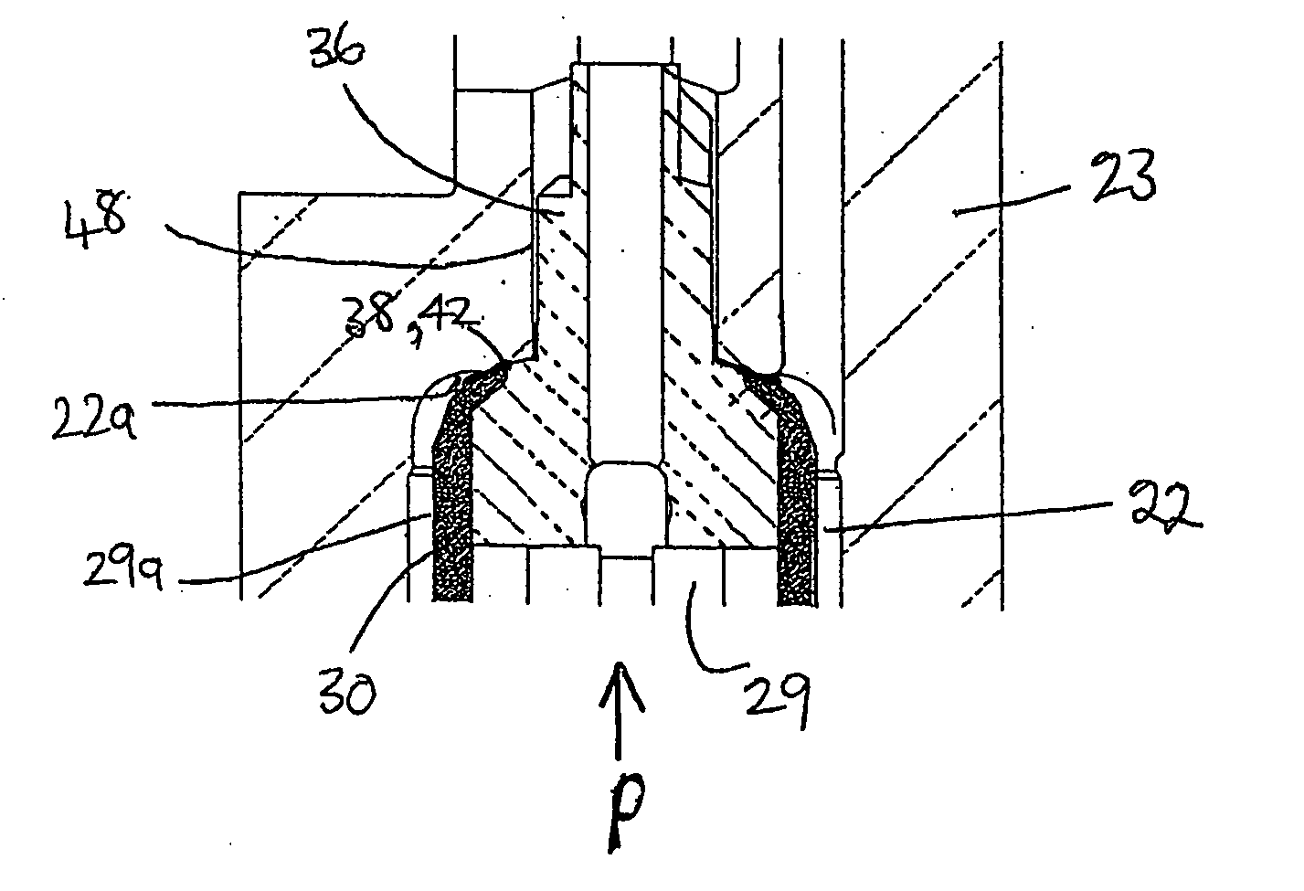
[0044] In the present invention, the sleeve member 30 is of a greater thickness in the region adjacent the shoulder portion 44 of the second terminal member 36 than in the other regions thereof. This region of greater thickness is referred to hereinafter as a volume of sealing material 42.

[0045] To form the seal member 38, heat is indirectly applied to the volume of sealing material 42 (i.e. the encapsulation material), and pressure is applied to the encapsulated actuator arrangement 29a in the same manner as described above. Alternatively, if the use of different materials to those described above is contemplated, different methods of indirectly heating the volume of sealing material 42 may be used.

[0046] In order to further improve the sealing function of the seal member 38, the ceiling end 22a of the accumulator volume 22, the longitudinal drilling 48 and the surface of the upper part of the encapsulated actuator arrangement 29a may be mechanically or chemically keyed to improve...


PUM


Abstract

A method of assembling a fuel injector (8) comprising a fuel injector body having an accumulator volume (22) defined therein is described. The method comprises: providing an encapsulated actuator arrangement (29a) having a piezoelectric actuator stack (29) and electrical connector means (34,36), wherein the stack (29) is encapsulated in a sleeve member (30); providing a volume of sealing material (42) in the region of the electrical connector means (34,36); locating the encapsulated actuator arrangement (29a) in the accumulator volume (22); applying heat indirectly to the volume of sealing material (42) so as to soften the volume of sealing material; and applying pressure to the encapsulated actuator arrangement (29a) such that the volume of sealing material (42) deforms to form a substantially fluid-tight seal (38) between the encapsulated actuator arrangement (29a) and the accumulator volume (22) in the region of the electrical connector means (34,36).

Description

TECHNICAL FIELD [0001] The present invention relates to a method of assembling a fuel injector for use in a fuel system of an internal combustion engine, particularly a fuel system of the accumulator or common rail type, the fuel injector being of the type controlled using a piezoelectric actuator. BACKGROUND ART [0002] In a known piezoelectrically actuated fuel injector, a piezoelectric actuator arrangement is operable to control the position occupied by a control piston, the piston being moveable to control the fuel pressure within a control chamber defined, in part, by a surface associated with the injector valve needle to control movement of the needle. The piezoelectric actuator typically includes a stack of piezoelectric elements, the axial length of which is controlled by applying a voltage across the stack through an electrical connector. It is known to arrange the piezoelectric stack within an accumulator volume which is arranged to receive high pressure fuel, in use, so as...

Claims


Application Information

Patent Timeline
Patent Type & Authority Applications(United States)
IPC IPC(8): B05B1/08F02M51/00F02M51/06F02M61/16F02M61/20F02M63/00H01L41/08H02N2/00
CPCF02M51/005F02M51/0603F02M2200/707F02M2200/215F02M61/165
Inventor BERLEMONT, JEAN-FRANCOIS
Owner DELPHI TECH INC
Why Eureka
Try Eureka