Semiconductor stack package and memory module with improved heat dissipation

a technology of memory modules and semiconductors, applied in the direction of semiconductor devices, semiconductor/solid-state device details, electrical devices, etc., can solve the problems of poor heat dissipation of above-described stack packages, poor heat conductivity of air, and low heat dissipation seriousness, so as to improve heat dissipation and improve heat dissipation. the effect of improving the heat dissipation path and eliminating unfavorable air gaps

Active Publication Date: 2005-09-15
SAMSUNG ELECTRONICS CO LTD
View PDF9 Cites 21 Cited by
  • Summary
  • Abstract
  • Description
  • Claims
  • Application Information

AI Technical Summary

Benefits of technology

[0013] Exemplary, non-limiting embodiments of the present invention provide a semiconductor stack package and a related memory module having improved heat di...

Problems solved by technology

However, the above-described stack packages have poor heat dissipation because unfavorable air gaps 18 (shown in FIGS.
This is caused by relatively poor heat conductivity of air and a heat-trapping phenomenon occurring in the air gap.
Such low heat dissipation becomes serious as the number of the i...

Method used


Image

  • Semiconductor stack package and memory module with improved heat dissipation
  • Semiconductor stack package and memory module with improved heat dissipation
  • Semiconductor stack package and memory module with improved heat dissipation

Examples


first exemplary embodiment

[0036] A cross-section of a stack package in accordance with a first exemplary embodiment of the present invention is shown in FIG. 6. The stack package 100, shown in FIG. 6, has a two-layered structure in which two individual packages 110a and 110b are arranged in layers. A lower individual package 110a has the same configuration as an upper individual package 110b. A cross-section of each individual package is shown in FIG. 7A. Furthermore, FIGS. 7B and 7C show, in plan views, bottom and top configurations of the individual package shown in FIG. 7A.

[0037] Referring to FIGS. 6, 7A, 7B and 7C, each individual package 110 includes an integrated circuit (IC) chip 111 that is attached to a circuit substrate 112. The circuit substrate 112 has a top face 112b to which the IC chip 111 is attached, and a bottom face 112a opposite the top face 112b. The circuit substrate 112 also has a central opening that extends lengthwise. The IC chip 111 has chip pads (not shown) that are formed on an ...

second exemplary embodiment

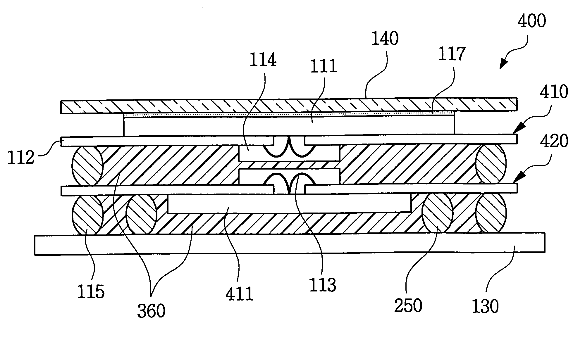
[0045] A cross-section of a stack package in accordance with a second exemplary embodiment of the present invention is shown in FIG. 8. The stack package 200, shown in FIG. 8, has a four-layered structure in which four individual packages 210a, 210b, 210c and 210d are arranged in layers. Each individual package 210a, 210b, 210c and 210d has the same configuration as described in the foregoing embodiment.

[0046] The stack package 200 particularly includes a plurality of dummy balls 250 that are provided between the lowermost individual package 210a and the module board 130. FIG. 9 shows, in a plan view, a bottom configuration of the lowermost individual package 210a.

[0047] Referring to FIGS. 8 and 9, the dummy balls 250 are formed in rows at the heat-conducting layer 116 on the bottom face of the circuit substrate 112, creating additional heat-dissipating paths from the lowermost individual package 210a to the module board 130. Thus, the heat dissipation of the stack package 200 can...

third exemplary embodiment

[0048] A cross-section of a stack package in accordance with a third exemplary embodiment of the present invention is shown in FIG. 10. The stack package 300, shown in FIG. 10, has a two-layered structure in which two individual packages 310 and 320 are arranged in layers. Unlike the foregoing embodiments, the upper and lower individual packages 310 and 320 are slightly different from each other in configuration.

[0049] Referring to FIG. 10, the upper individual package 310 has a configuration that the active surface of the IC chip 111 is attached to the top face of the circuit substrate 112, whereas the lower individual package 320 has an opposite configuration with the active surface of the IC chip 111 attached to the bottom face of the circuit substrate 112. All the solder balls 115 of both individual packages 310 and 320 are still provided on the bottom face of the respective circuit substrates 112.

[0050] Particularly, each of the IC chips 111 faces the outside of the stack pac...


PUM


Abstract

A semiconductor stack package includes lower and upper individual packages. When the upper individual package is stacked on the lower individual package, a heat-conducting layer provided under the upper package touches a heat-mediating layer provided on the lower package. Thus, a layer of trapped air found in conventional stack packages is eliminated, and a direct heat-dissipating path is produced through both the heat-conducting layer and the heat-mediating layer. Therefore, the heat dissipation of the stack package is improved. Alternatively, the stack package may have a symmetric configuration in which each IC chip faces away from each other. A memory module has several stack packages mounted on one or both surfaces of a module board. The method includes forming the packages and stacking the packages. The method further includes forming a module board and mounting the stack packages on the module board.

Description

CROSS REFERENCE TO RELATED APPLICATIONS [0001] This U.S. non-provisional application claims priority under 35 U.S.C. §119 to Korean Patent Application No. 2004-16902 filed Mar. 12, 2004, the contents of which are incorporated herein in its entirety by reference. BACKGROUND OF THE INVENTION [0002] 1. Field of the Invention [0003] The present invention relates generally to electronic packaging technology and, more particularly, to a three-dimensional semiconductor stack package and a memory module using the stack packages. [0004] 2. Description of the Related Art [0005] In general, a semiconductor package is defined as the housing and interconnection of integrated circuits, also referred to as chips or die, to form an electronic system. One of the functions that the package provides is to remove heat generated by the chips or system. Therefore heat dissipation becomes a much more important factor that must be considered during the design or fabrication of the packages, especially in v...

Claims


Application Information

Patent Timeline
IPC IPC(8): H01L23/02H01L23/28H01L23/48H01L23/34
CPCH01L21/563H01L23/13H01L2225/1005H01L2224/32225H01L2924/3511H01L2924/01033H01L2924/01006H01L24/48H01L2924/15321H01L2924/15311H01L2924/01029H01L2924/01013H01L23/3128H01L23/36H01L23/49816H01L24/32H01L24/73H01L25/0652H01L25/105H01L2224/29099H01L2224/4824H01L2224/73215H01L2224/73265H01L2224/83856H01L2225/1023H01L2225/1058H01L2225/1094H01L2924/00014H01L2924/00012H01L2924/00H01L2224/451H01L24/45H01L2924/14H01L2924/00015H01L2224/05599H01L23/34
Inventor BAEK, JOONG-HYUNPARK, SANG-WOOKLEE, HAE-HYUNG
Owner SAMSUNG ELECTRONICS CO LTD
Why Eureka
Try Eureka