Vehicular occupant protection device

Inactive Publication Date: 2005-09-15
DENSO CORP
View PDF8 Cites 13 Cited by
  • Summary
  • Abstract
  • Description
  • Claims
  • Application Information

AI Technical Summary

Benefits of technology

[0008] It is an object of the present invention to provide a vehicular occupant protection device that is compact and low in cost by decreasing the number of components while securing the capability of protecting noises.
[0009] To achieve the above object, a vehicular occupant protection device is provided with the following. An ignition element is included for being ignited by an ignition current. An ignition circuit is included for supplying the ignition current to the ignition element. A noise protection circuit is included for having two zener diodes so that their cathodes are facing each other and connected with each other. Here, the noise protection circuit is connected in parallel with the ignition circuit to thereby protect the ignition circuit from noise.
[0010] In this structure, the noise protection circuit including the two zener diodes protects the ignition circuit from noise. Further, when noise is conducted and interferes with the ignition element, high voltage is sometimes induced. However, under the above structure, the noise protection circuit including the two zener diodes suppresses the high voltage to the voltage determined by the sum of zener voltage of one zener diode and forward directional voltage of the other zener diode. Therefore, the high voltage is not applied to the ignition circuit electrically connecting to the ignition element, so that this helps prevent the ignition circuit from damage. Further, in comparison with the conventional noise protection circuit including three zener diodes, the number of components is decreased, so that the vehicular occupant protection device can be compact and low in cost while securing the noise protection capability.

Problems solved by technology

Further, when noise is conducted and interferes with the ignition element, high voltage is sometimes induced.

Method used


Image

  • Vehicular occupant protection device
  • Vehicular occupant protection device
  • Vehicular occupant protection device

Examples


Embodiment Construction

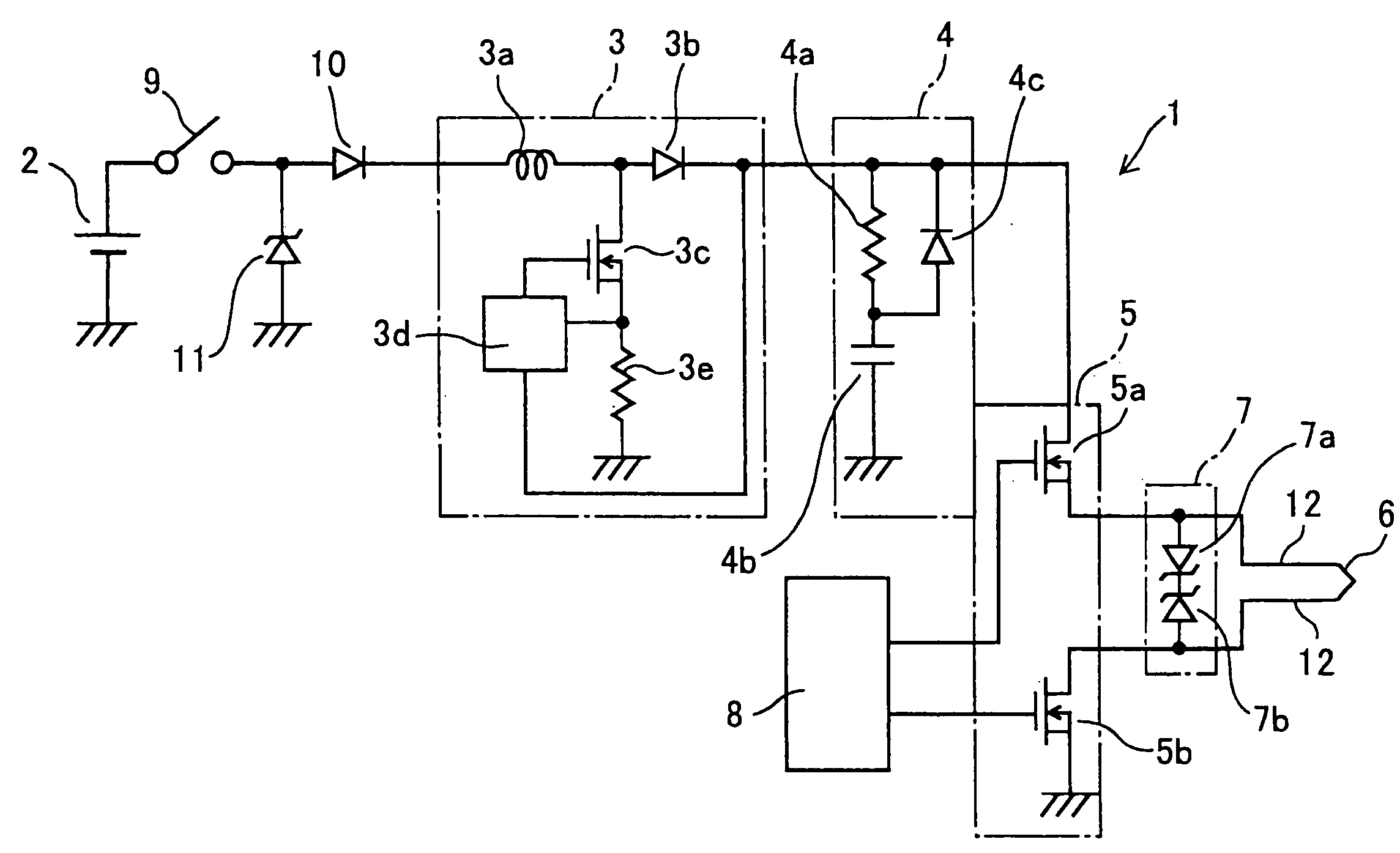
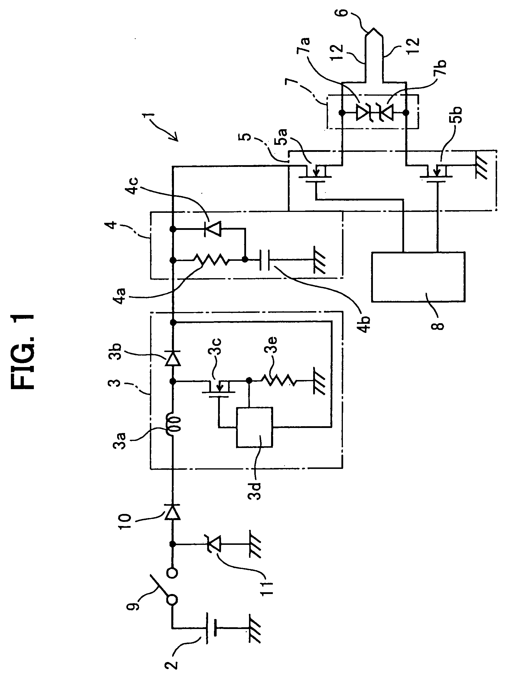
[0018] The present invention of a vehicular occupant protection device is directed to an airbag device, which will be explained with reference to drawings. This airbag device 1 includes a battery 2, a voltage-increase circuit 3, a backup-power circuit 4, an ignition circuit 5, a squib (ignition element) 6, a noise protection circuit 7, and a micro-computer 8.

[0019] The battery 2 is, e.g., a direct-current power source. The positive terminal of the battery 2 connects with one end of an ignition switch 9, while the negative terminal is grounded to a vehicle body. The other end of the ignition switch 9 connects with the anode of a diode 10; the cathode of the diode 10 connects with the voltage-increase circuit 3. Further, a zener diode 11 of 35 V or the like is connected between the ignition switch 9 and the diode 10. This zener diode 11 suppresses surge voltage of load-dump surge due to rapid decrease in electrical loads connected to the battery 2.

[0020] The voltage-increase circuit...


PUM


Abstract

An airbag device includes a squib, an ignition circuit, and a noise protection circuit. The noise protection circuit includes two zener diodes whose cathodes are facing each other and connected with each other. Further, the noise protection circuit is connected in parallel with the ignition circuit to thereby protect the ignition circuit from noise. This decrease the number of components in the noise protection circuit to thereby achieve the compact and low-cost airbag device.

Description

CROSS REFERENCE TO RELATED APPLICATIONS [0001] This application is based on and incorporates herein by reference Japanese Patent Application No. 2004-70888 filed on Mar. 12, 2004. FIELD OF THE INVENTION [0002] The present invention relates to a vehicular occupant protection device. BACKGROUND OF THE INVENTION [0003] There is a conventional activation device for a vehicular protection system disclosed in Patent Document 1. This activation device includes an acceleration sensor, a micro-computer, a squib (ignition element), two electronic switching elements, and a driving circuit that drives the foregoing components. [0004] Patent Document 1: JP-2001-239916 (US-2001 / 0006309 A1, U.S. Pat. No. 6,465,907 B2) [0005] The acceleration sensor detects impact from vehicle collision; then, the micro-computer turns on the two electronic switching elements via the driving circuit based on the detection result by the acceleration sensor. Thus, ignition current is conducted to the squib from a dire...

Claims


Application Information

Patent Timeline
IPC IPC(8): B60L3/00B60R21/16
CPCB60R21/017
Inventor UONO, YUTAKAASO, MAKOTO
Owner DENSO CORP
Why Eureka
Try Eureka