Surface light source device and back light unit having the same

Inactive Publication Date: 2005-09-15
SAMSUNG CORNING CO LTD
View PDF0 Cites 6 Cited by
  • Summary
  • Abstract
  • Description
  • Claims
  • Application Information

AI Technical Summary

Benefits of technology

[0022] The present invention provides a surface light source device having an improved luminance by suppressing formation of a parasite capacitance in partition walls.
[0023] The present invention also provides a surface light source device including discharge spaces, which have an optimal aspect ratio established for optimizing loss of plasma, by reducing contact between the discharge spaces and the plasma.
[0032] A back light unit in accordance with still another aspect of the present invention includes a surface light source device, a case for receiving the surface light source device, an optical sheet interposed between the surface light source device and the case, and an inverter for applying a discharge voltage to the surface light source device. The surface light source device includes a light source body having an inner space into which a discharge gas is injected, and an electrode for applying a voltage to the discharge gas. The light source body includes partition walls dividing the inner space into a plurality of discharge spaces. The partition walls have a width for suppressing formation of the parasite capacitance through which a current flows in the partition walls.
[0033] According to the present invention, the partition walls have the width for suppressing formation of the parasite capacitance in the partition walls so that the current drift effect generated between the adjacent discharge spaces may be remarkably reduced. Thus, the surface light source device may be improved luminance. Also, the discharge spaces have the aspect ratio of about 2.5:1 to about 6:1. That is, the discharge spaces have a height and a width of about 2.5 times the height. Thus, the plasma may make contact with upper and lower faces of the discharge spaces without making contact with side faces of the discharge spaces so that the ambipolar diffusion loss of the plasma may be reduced for better lighting efficiency.

Problems solved by technology

The CCFL has high luminance and long lifespan, and generates small amount of heat.
However, both of the CCFL and the LED have low uniformity of luminance.
However, in the conventional surface light source device, as the partition walls have the width of no more than about 1 mm, an interval between adjacent discharge spaces is narrowed, which causes a parasite capacitance to be formed in the partition walls.
A current flows to adjacent discharge spaces through the parasite capacitance so that the current drift effect is excessively generated.
As a result, the luminance uniformity of the surface light source device is deteriorated.
Thus, the plasma makes contact with side faces of the discharge space as well as upper and lower faces of the discharge space so that the plasma suffers excessive loss at the side faces and the upper and lower faces of the discharge space.
As a result, the conventional surface light source device has a low light-generating efficiency.

Method used


Image

  • Surface light source device and back light unit having the same
  • Surface light source device and back light unit having the same
  • Surface light source device and back light unit having the same

Examples


embodiment 1

[0052] Embodiment 1

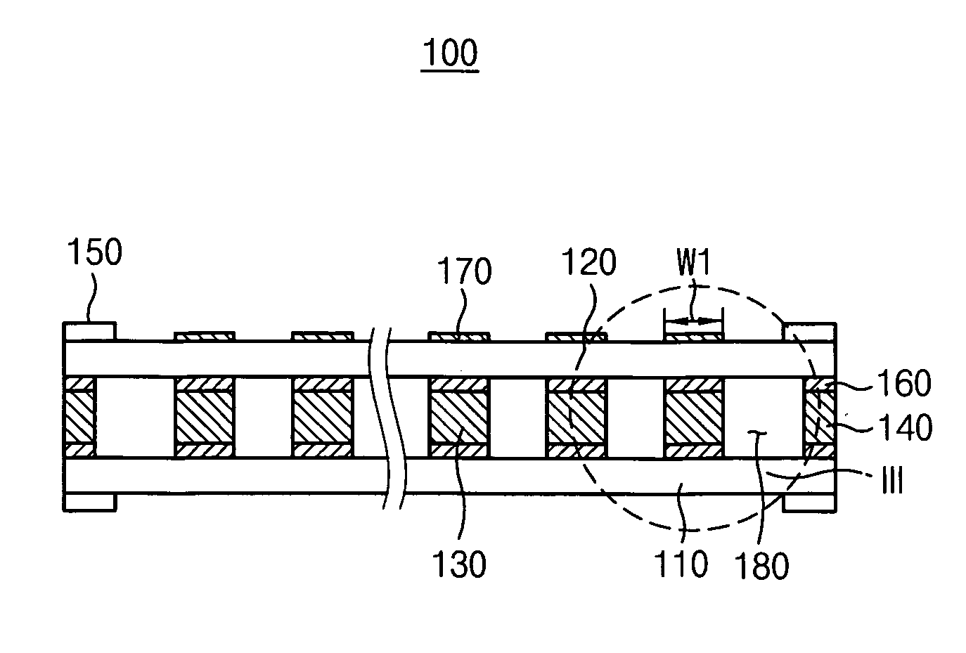
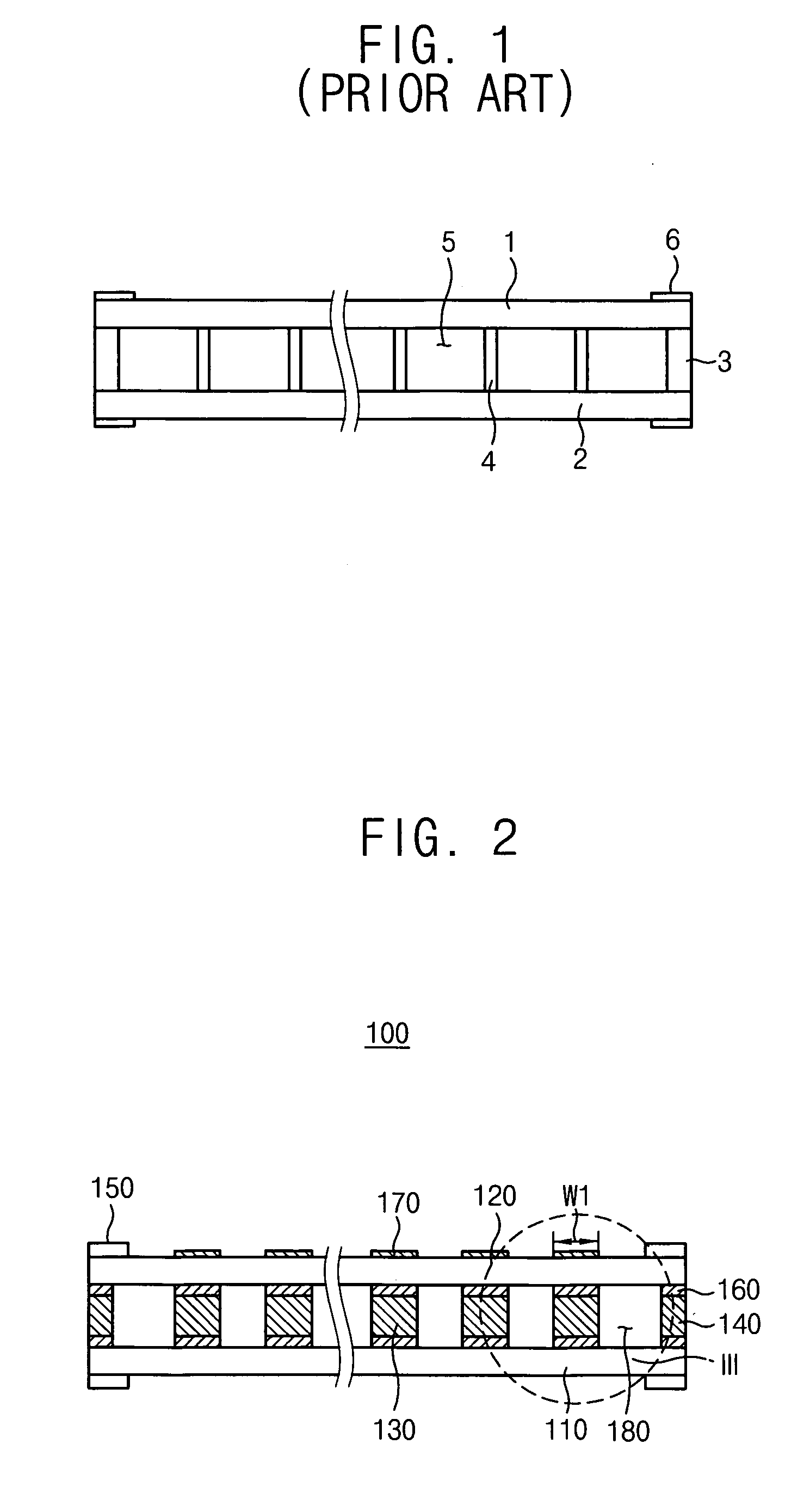
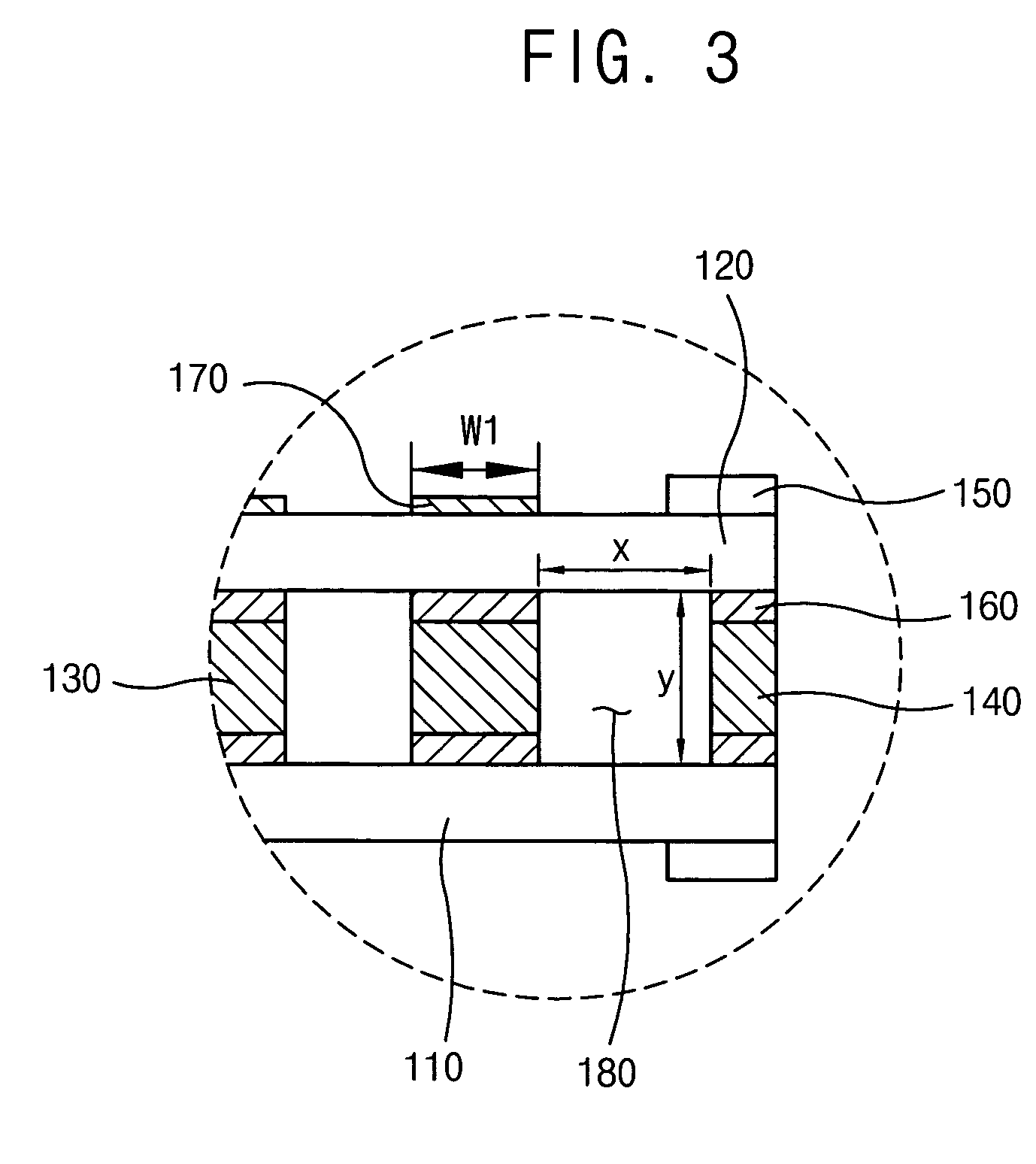
[0053]FIG. 2 is a cross sectional view illustrating a surface light source device in accordance with a first embodiment of the present invention and FIG. 3 is an enlarged cross sectional view illustrating a portion III in FIG. 2.

[0054] Referring to FIGS. 2 and 3, a surface light source device 100 in accordance with the present embodiment includes a light source body having an inner space into which a discharge gas is injected, and an electrode 150 for applying a voltage to the discharge gas. Here, examples of the discharge gas are a mercury gas, an argon gas, a neon gas, a xenon gas, etc.

[0055] The light source body is a partition wall-separated type. Thus, the light source body includes a first substrate 110 and a second substrate 120 positioned over the first substrate 110. A sealing member 140 is interposed between edge portions of the first and second substrates 110 and 120 to define the inner space. Partition walls 130 are arranged in the inner space to div...

embodiment 2

[0067] Embodiment 2

[0068]FIG. 4 is a cross sectional view illustrating a surface light source device in accordance with a second embodiment of the present invention and FIG. 5 is an enlarged cross sectional view illustrating a portion V in FIG. 4;

[0069] Referring to FIGS. 4 and 5, a surface light source device 200 in accordance with the present embodiment includes a light source body having an inner space into which a discharge gas is injected, and an electrode 260 for applying a voltage to the discharge gas.

[0070] The light source body is a partition wall-integrated type. Thus, the light source body includes a first substrate 210 and a second substrate 220 positioned over the first substrate 210. The second substrate 220 has partition wall portions 212 attached to an upper face of the first substrate 210 using a frit 230. Thus, a plurality of discharge spaces 250 having an arch cross shape is formed between the first and second substrates 210 and 220.

[0071] The electrode 260 is ...

embodiment 3

[0075] Embodiment 3

[0076]FIG. 6 is a cross sectional view illustrating a surface light source device in accordance with a third embodiment of the present invention and FIG. 7 is an enlarged cross sectional view illustrating a portion VII in FIG. 6;

[0077] Referring to FIGS. 6 and 7, a surface light source device 300 in accordance with the present embodiment includes a light source body having an inner space into which a discharge gas is injected, and an electrode 360 for applying a voltage to the discharge gas.

[0078] The light source body includes a first substrate 310 having partition wall portions 312 and a second substrate 320 positioned over the first substrate 310. The partition wall portions 312 are attached to a lower face of the second substrate 320 to form discharge spaces 350.

[0079] The discharge spaces 350 have a width x and a height y. An aspect ratio of the discharge spaces 350, which corresponds to a ratio of the width x with respect to the height y, is about 2.5:1 t...


PUM


Abstract

A surface light source device includes a light source body having an inner space into which a discharge gas is injected, and an electrode for applying a voltage to the discharge gas. The light source body includes partition walls dividing the inner space into a plurality of discharge spaces. The partition walls have a width for suppressing formation of a parasite capacitance through which a current flows therein.

Description

CROSS-REFERENCE TO RELATED APPLICATION [0001] This application claims priority under 35 USC § 119 to Korean Patent Applications Nos. 2004-16398, filed on Mar. 11, 2004, 2004-40195, filed on Jun. 3, 2004, and 2005-11950, filed on Feb. 14, 2005, the contents of which are herein incorporated by reference in their entireties for all purposes. BACKGROUND OF THE INVENTION [0002] 1. Field of the Invention [0003] The present invention relates to a surface light source device and a back light unit having the same. More particularly, the present invention relates to partition walls dividing an internal space of a surface light source device into a plurality of discharge spaces, and a back light unit having the surface light source device as a light source. [0004] 2. Description of the Related Art [0005] Generally, a liquid crystal (LC) has specific electrical and optical characteristics. In detail, when electric fields applied to the LC are changed, an arrangement of the LC molecules is also ...

Claims


Application Information

Patent Timeline
IPC IPC(8): G02F1/13357F21S2/00F21Y105/00G02F1/1335H01J61/30H01J65/00H01K1/18
CPCG02F1/1336H01J61/305H01J65/00G02F1/133604
Inventor KIM, GEUN-YOUNGKO, JAE-HYEONLEE, KI-YEONKIM, DONG-WOOCHO, SEOG-HYUN
Owner SAMSUNG CORNING CO LTD
Why Eureka
Try Eureka