RFID device with patterned antenna, and method of making

a technology of patterned antennas and antennas, applied in the field of radio frequency identification (rfid) tags and labels, can solve the problems of significant cost barriers to more widespread use of such devices, one component of cost is the cost of materials for the antenna structure, etc., and achieve the effect of reducing the cost of rfid devices and reducing the cos

Active Publication Date: 2005-09-15
AVERY DENNISON CORP
View PDF13 Cites 51 Cited by
  • Summary
  • Abstract
  • Description
  • Claims
  • Application Information

AI Technical Summary

Benefits of technology

[0028] According to still another aspect of the invention, a method of reducing cost of radio frequency identification (RFID) devices, the method includes: selecting an initial antenna structure layout, wherein the initial antenna structure layout includes a conductive element of conductive material; and modifying a portion of the conductive element initial antenna structure layout to produce a modified antenna structure layout having a reduced cost associated therewith.

Problems solved by technology

The cost of RFID devices has been a significant barrier to more widespread use of such devices.
One component of the cost is the cost of materials for the antenna structure, such as the cost for the conductive ink that may be used to print the antenna structure.

Method used


Image

  • RFID device with patterned antenna, and method of making
  • RFID device with patterned antenna, and method of making
  • RFID device with patterned antenna, and method of making

Examples


Embodiment Construction

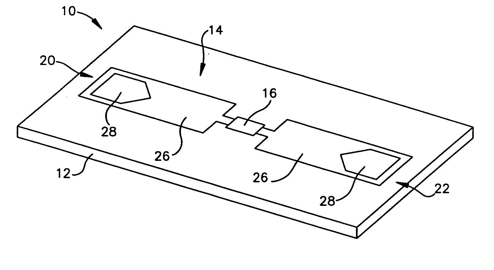
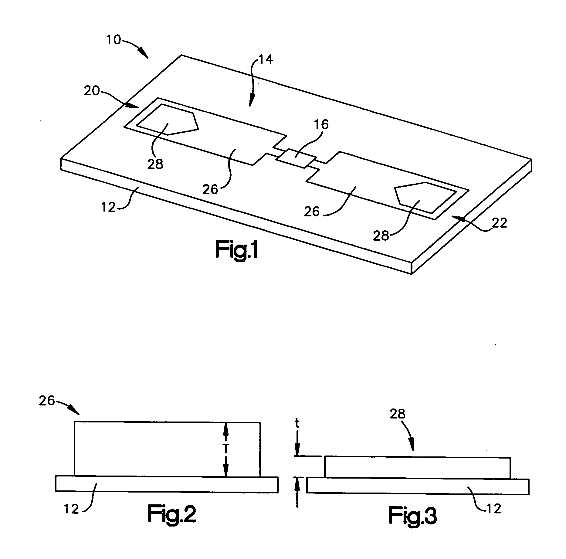
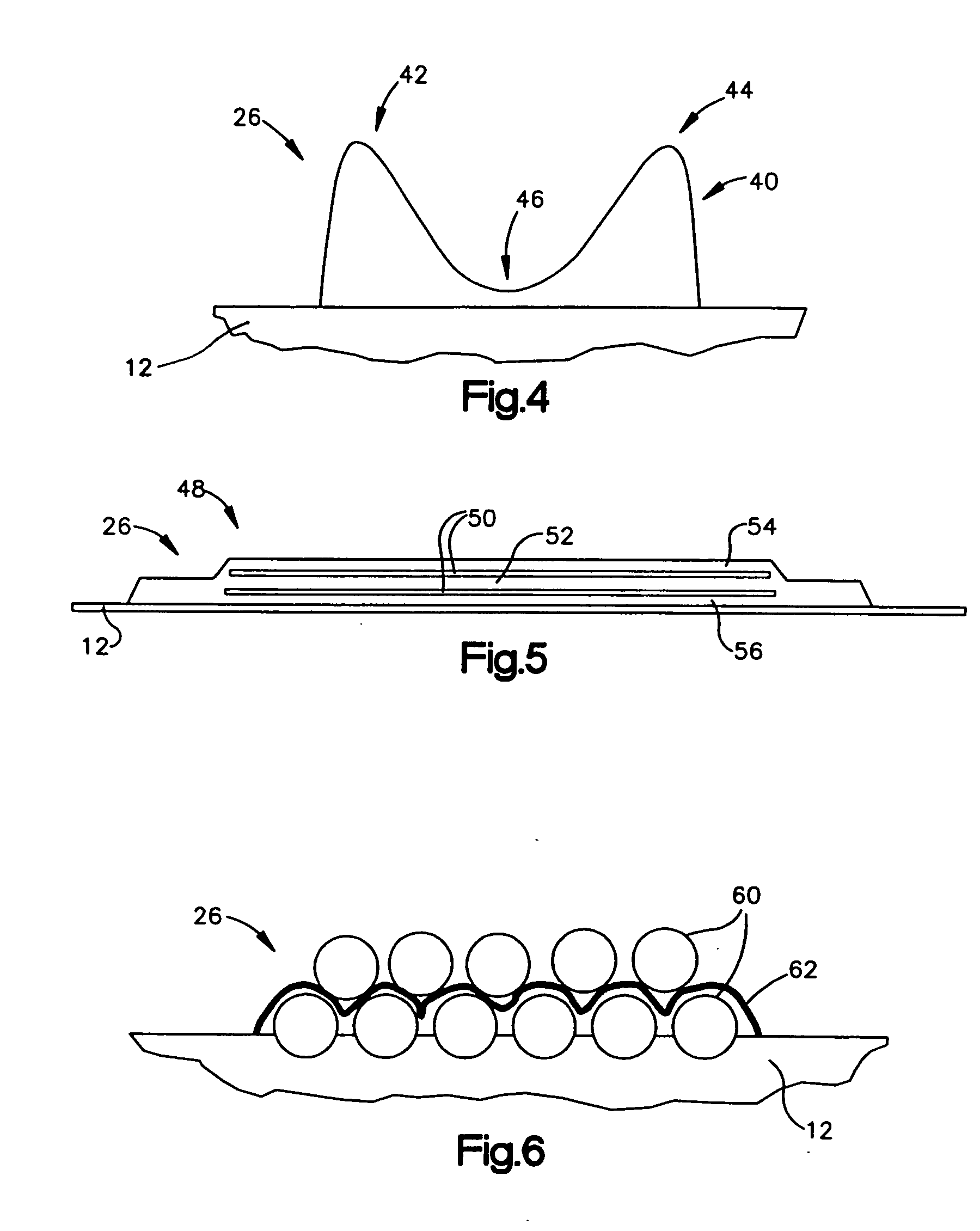
[0039] A radio frequency identification device (RFID) antenna structure includes electrically-conductive material. The antenna structure includes low effective resistance areas and high effective resistance areas. The high effective resistance areas are located in regions where there would be little current flow even if there were less effective resistance, such as the same resistance as the low effective resistance areas. The high effective resistance areas may be spaces within the antenna structure in which there is substantially no electrically conductive material. Alternatively, the high effective resistance areas may have some non-zero electrical conductivity, while still having a higher effective resistance than the low effective resistance areas. Conductive material for the antenna structure may include conductive ink. By reducing or eliminating the amount of conductive material in the high effective resistance areas, and / or by substituting less expensive conductive material,...


PUM

PropertyMeasurementUnit
current-flowaaaaaaaaaa
effective resistanceaaaaaaaaaa
conductivityaaaaaaaaaa

Abstract

A radio frequency identification device (RFID) antenna structure includes electrically-conductive material. The antenna structure includes low effective resistance-material areas and high effective resistance areas in regions where there would be little current flow if there were more low effective resistance material. The high effective resistance areas may be spaces within the antenna structure in which there is substantially no electrically conductive material. Alternatively, high effective resistance material in the high effective resistance areas may have a non-zero lower electrical conductivity than the low effective resistance material in the low effective resistance-material areas. Conductive material for the antenna structure may include conductive ink. By reducing or eliminating the amount of conductive material in the high effective resistance areas, it will be appreciated that reduced-cost devices may be obtained.

Description

BACKGROUND OF THE INVENTION [0001] 1. Field of the Invention [0002] This invention relates to the field of Radio Frequency Identification (RFID) tags and labels, and in particular to antenna structures for such tags and labels, and methods of reducing costs of antenna structures. [0003] 2. Description of the Related Art [0004] Radio frequency identification (RFID) tags and labels (collectively referred to herein as “devices”) are widely used to associate an object with an identification code. RFID devices generally have a combination of antennas and analog and / or digital electronics, which may include for example communications electronics, data memory, and control logic. For example, RFID tags are used in conjunction with security-locks in cars, for access control to buildings, and for tracking inventory and parcels. Some examples of RFID tags and labels appear in U.S. Pat. Nos. 6,107,920, 6,206,292, and 6,262,292, all of which are hereby incorporated by reference in their entireti...

Claims


Application Information

Patent Timeline
Patent Type & Authority Applications(United States)
IPC IPC(8): G06K19/077H01Q1/22H01Q1/38H01Q9/04
CPCG06K19/07749G06K19/07786H01Q1/22Y10T29/49016H01Q1/38H01Q9/0407H01Q1/2225G06K19/07H01Q9/04
Inventor FORSTER, IAN J.ROBERTS, BARRY J.
Owner AVERY DENNISON CORP
Why Eureka
Try Eureka