Objective optical element and optical pickup apparatus

a pickup apparatus and optical element technology, applied in the field of optical pickup apparatus, can solve problems such as lightening design load, and achieve the effect of lightening design load and lightening design burden

Inactive Publication Date: 2005-09-15
KONICA MINOLTA OPTO
View PDF5 Cites 10 Cited by
  • Summary
  • Abstract
  • Description
  • Claims
  • Application Information

AI Technical Summary

Benefits of technology

[0013] The present invention is attained in view of problems of the conventional technology, and an object of the invention is to provide an objective optical element by which a fine spherical aberration correction can be conducted, even when light fluxes having 3 different wavelengths are incident.
[0014] An objective optical pickup apparatus relating to the present invention, corrects spherical aberration or wavefront aberration by providing optical path difference so as to change phase amount only for the light flux with wavelength λ3 using the first diffractive structure. Further, the objective optical pickup apparatus corrects spherical aberration or wavefront aberration by providing optical path difference for the light fluxes with wavelengths λ1 and λ2 using the second diffractive structure. It lighten design load caused by a problem in conventional technique and the whole system of the optical pickup apparatus conducts information recording and / or reproducing properly by correcting aberration for the three light fluxes with different wavelengths. It lightens the burden on designing caused by the problem in the conventional technique, and records and / or reproduces information properly by correcting the aberration totally conducted for all of light fluxes with 3 different wavelengths.

Problems solved by technology

It lighten design load caused by a problem in conventional technique and the whole system of the optical pickup apparatus conducts information recording and / or reproducing properly by correcting aberration for the three light fluxes with different wavelengths.

Method used


Image

  • Objective optical element and optical pickup apparatus
  • Objective optical element and optical pickup apparatus
  • Objective optical element and optical pickup apparatus

Examples


example 1

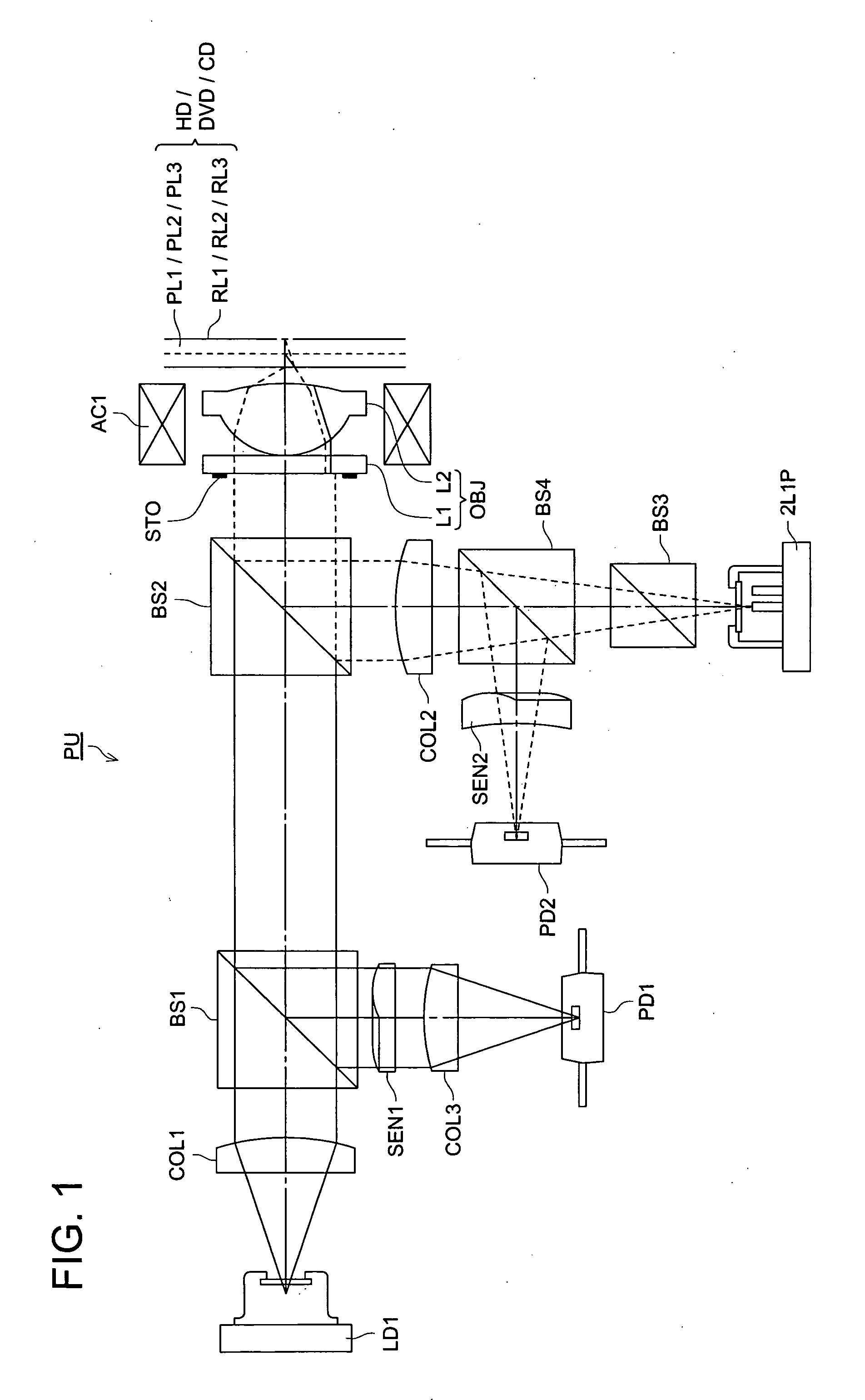
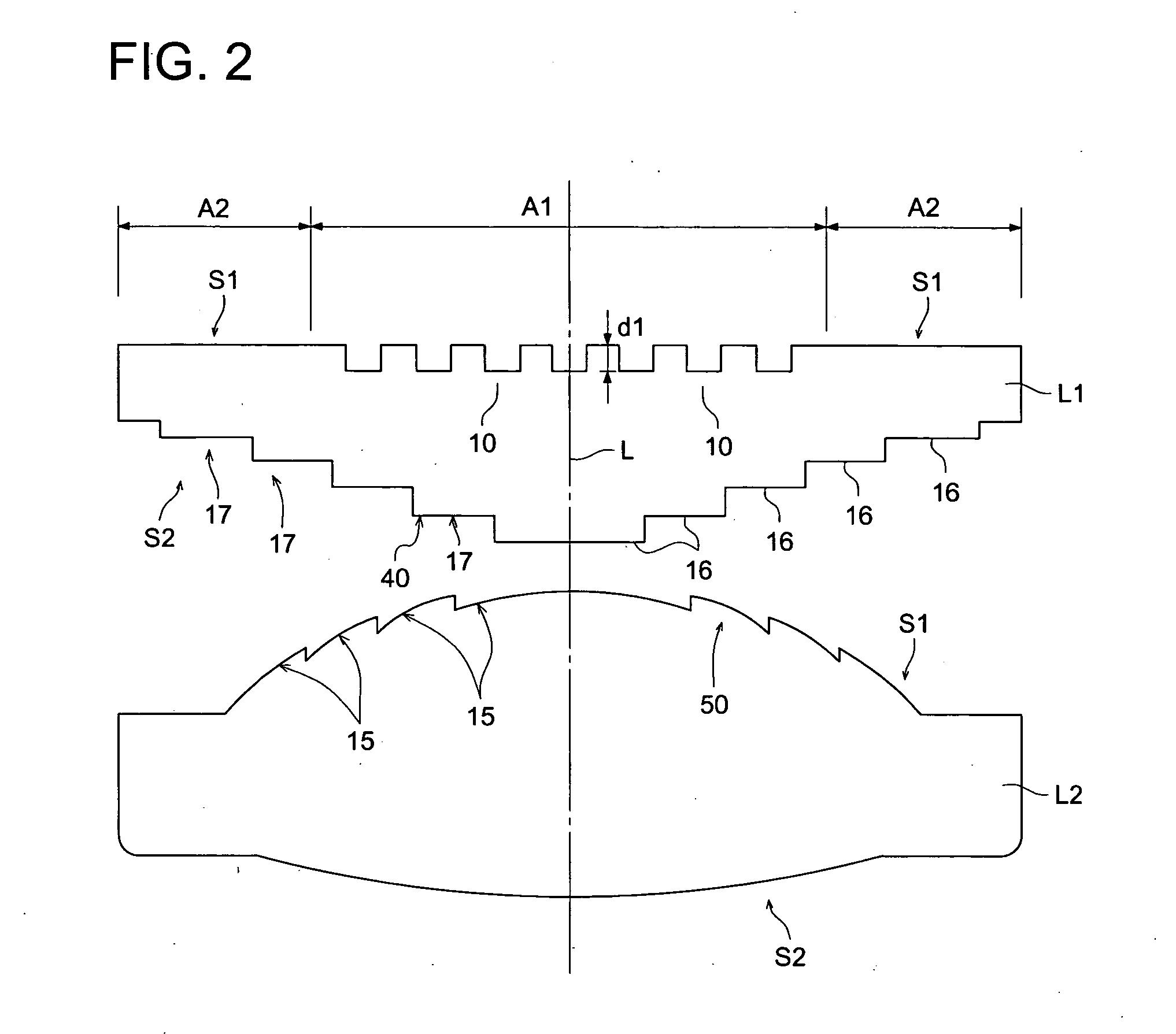
[0114] Next, examples will be described. In the present example, as shown in FIG. 2, the objective optical element OBJ is composed of the aberration correction element L1 and the light converging element L2. The incident surface S1 (the 3rd surface) of the aberration correction element is a plane, and the outgoing surface S2 (4th surface) is formed of an aspheric surface, and the incident surface S1 (the 4th surface) and the outgoing surface S2 (the 5th surface) of the light converging element L2 are formed of aspheric surface.

[0115] The first diffractive structure 10 (first phase difference providing structure) is formed on the incident surface S1 of the aberration correction element L1, and the third optical path difference providing structure is formed on the emerging surface S2 of the aberration correction element L1. The second diffractive structure 50 (second phase difference providing structure) whose sectional shape including the optical axis is serrated shape is formed on ...


PUM

PropertyMeasurementUnit
wavelength conversionaaaaaaaaaa
wavelengthsaaaaaaaaaa

Abstract

An objective optical element for use in an optical pickup apparatus first-third light sources emitting first-third light fluxes and a light converging optical system, includes a first optical path difference providing structure for providing an optical path difference which provides a substantial phase change to the third light flux and does not provide a substantial phase change to the first and second light fluxes; and a second optical path difference providing structure for providing an optical path difference to the first light flux, the second light flux and the third light flux, wherein the objective optical element converges the first-third light fluxes through the protective layers with the thicknesses t1-t3 onto an information recording surface of the first-third optical information media respectively.

Description

FIELD OF THE INVENTION [0001] The present invention relates to an optical pickup apparatus, and particularly, to an optical pickup apparatus which can recording and / or reproducing information respectively on 3 or more different optical information recording media by using light fluxes with different wavelengths emitted from 3 light sources. BACKGROUND OF THE INVENTION [0002] Recently, in the optical pickup apparatus, the wavelength-shortening of the laser light source used as the light source for reproducing of the information recorded in an optical disk or recording of the information in the optical disk is advanced. For example, a laser light source of wavelength 405 nm such as a blue-violet semiconductor laser, or a blue-violet SHG laser which conducts the wavelength conversion of the infrared semiconductor laser by using the second harmonic wave generation is putting to a practical use. [0003] When these blue-violet laser light sources are used, in the case where an objective le...

Claims


Application Information

Patent Timeline
Patent Type & Authority Applications(United States)
IPC IPC(8): G02B5/18G02B13/18G11B7/00G11B7/135
CPCG11B7/1353G11B7/1367G11B2007/0006G11B7/13922G11B7/1374G02B13/00G02B5/18
Inventor MIMORI, MITSURUHASHIMURA, JUNJIIKENAKA, KIYONO
Owner KONICA MINOLTA OPTO
Why Eureka
Try Eureka