Implants

Inactive Publication Date: 2005-09-15
ACTIVE IMPLANTS LLC
View PDF99 Cites 75 Cited by
  • Summary
  • Abstract
  • Description
  • Claims
  • Application Information

AI Technical Summary

Benefits of technology

[0072] In addition to the enhanced bone adhesion methods described herein, the contact surface of an artificial implantation device may also be treated using one of the following Surface Modification processes: Atomic cleaning, adhesion promotion, molecular grafting, cell attachment

Problems solved by technology

The biological response to a certain extreme stress magnitude does not generate the growth of new bone cells but causes bone resorption.
Therefore it can be stated that temporal and spatial regulation of loads may result in bone remodeling and overall increase of bone mass.
It is further kn

Method used


Image

  • Implants
  • Implants
  • Implants

Examples


Embodiment Construction

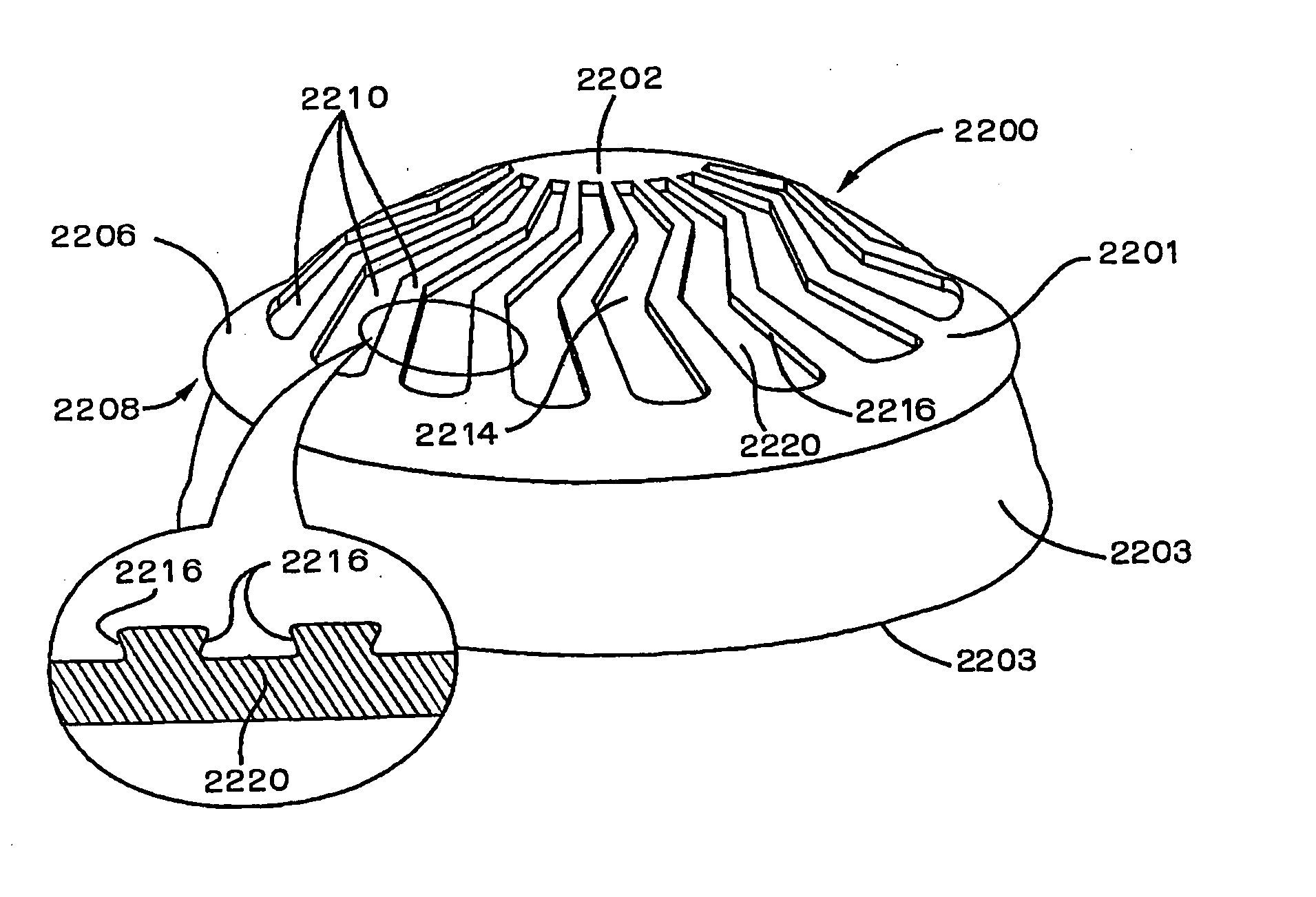
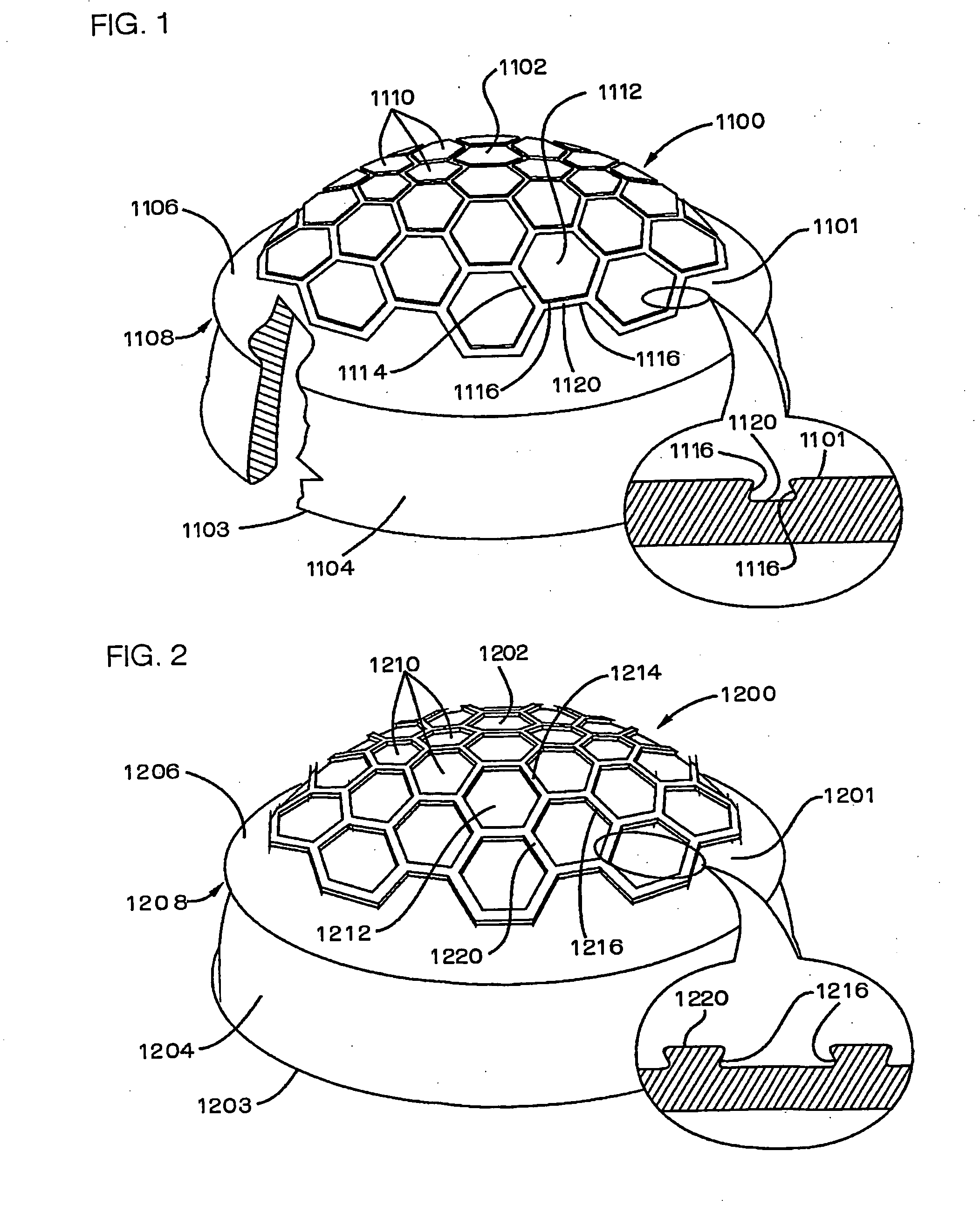
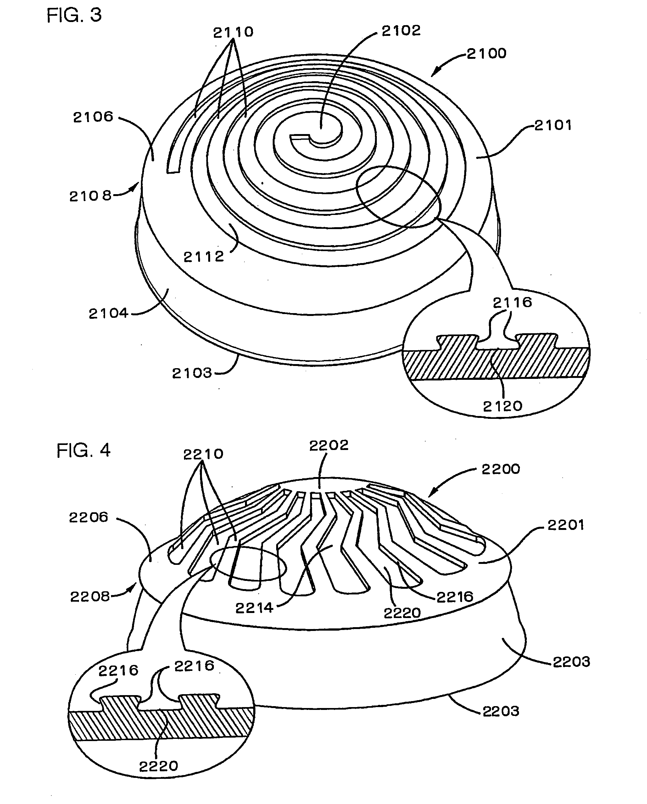
[0095] Reference is now made to FIG. 1, which is a pictorial illustration of an implantable artificial socket constructed and operative in accordance with a preferred embodiment of the present invention and which is particularly suitable for use in a hip joint. The embodiment of FIG. 1 is particularly directed to providing an anchoring mechanism on a bone-engaging surface of the artificial socket for enhancing the anchoring and adhesion of the socket to the bone and thus improving the stability and longevity of the prosthesis.

[0096] As seen in FIG. 1, an implantable artificial socket, designated by reference numeral 1100, is formed preferably by injection molding of a bio stable and bio compatible pliable material such as an elastomer, preferably polyurethane, having mechanical properties which are characterized by a nonlinear stress strain relationship.

[0097] Preferably, implantable artificial socket 1100 is of generally uniform thickness and defines a generally hemispherical con...


PUM

PropertyMeasurementUnit
Mechanical propertiesaaaaaaaaaa
Dimensionaaaaaaaaaa
Stabilityaaaaaaaaaa

Abstract

An implantable prosthesis including at least one element defining a bone-engaging surface, the bone-engaging surface including an anchoring mechanism operative for enhancing anchoring and adhesion of the joint defining element to the bone and thus improving the stability and longevity of the prosthesis.

Description

REFERENCE TO RELATED APPLICATIONS [0001] This application is partially based upon and claims priority from: [0002] U.S. Provisional Patent Application Ser. No. 60 / 383,483 filed May 23, 2002 and entitled “JOINT IMPLANTS SYSTEM AND METHODOLOGY AND IMPLANTS AND TOOLS USEFUL THEREWITH”; and PCT Patent Application Serial No. PCT / IL02 / 00972 filed on Dec. 3, 2002 and entitled: “CUSHION BEARING IMPLANTS FOR LOAD BEARING APPLICATIONS”; and PCT Patent Application Serial No. PCT / IL03 / 00063.A filed on Jan. 24, 2003 and entitled: “JOINT PROSTHESIS”FIELD OF THE INVENTION [0003] The present invention relates generally to implants and methods relating thereto. BACKGROUND OF THE INVENTION [0004] The following patents are believed to be relevant to the subject matter of this application: U.S. Pat. Nos. 5,201,881; 5,011,497; 4,279,041; 5,080,675; 4,650,491;3,938,198; 4,292,695; 4,624,674; 2,765,787; 4.735,625; 5,370,699; 5,641,323;5,323,765; 5,658,345; 3,875,594; 3,938,198; 4,292,695; 4,344,193; 4,57...

Claims


Application Information

Patent Timeline
IPC IPC(8): A61C8/00A61F2/00A61F2/28A61F2/30A61F2/32A61F2/34A61F2/36A61F2/38A61L27/18
CPCA61C8/00A61F2310/00796A61C8/0018A61C8/0036A61F2/30756A61F2/30767A61F2/30771A61F2/32A61F2/34A61F2/38A61F2/3859A61F2/389A61F2002/30069A61F2002/3007A61F2002/30143A61F2002/30144A61F2002/30243A61F2002/30289A61F2002/30291A61F2002/30322A61F2002/30332A61F2002/305A61F2002/30563A61F2002/30614A61F2002/30652A61F2002/30673A61F2002/3082A61F2002/30822A61F2002/30823A61F2002/30827A61F2002/30883A61F2002/30906A61F2002/30934A61F2002/30947A61F2002/30957A61F2002/30981A61F2002/342A61F2002/3422A61F2002/3464A61F2002/3611A61F2002/365A61F2220/0025A61F2220/0033A61F2230/0017A61F2230/0071A61F2230/0091A61F2250/0026A61C8/0012A61F2002/30943A61F2002/3462A61F2/3094
Inventor MCGUIRE, JOHN
Owner ACTIVE IMPLANTS LLC
Why Eureka
Try Eureka