Atraumatic arthroscopic instrument sheath

a technology of arthroscopic instruments and sheaths, applied in the field of arthroscopic surgical instruments, can solve the problems of reducing the surgical field, the need for many surgical instruments, and the number of incisions or portals required for minimally invasive surgery, so as to achieve clear surgical field and keep surgical field clear

a technology of arthroscopic instruments and sheaths, applied in the field of arthroscopic surgical instruments, can solve the problems of reducing the surgical field, the need for many surgical instruments, and the number of incisions or portals required for minimally invasive surgery, so as to achieve clear surgical field and keep surgical field clear

US20050203342A1Active Publication Date: 2005-09-15PRISTINE SURGICAL LLC

Image

  • Atraumatic arthroscopic instrument sheath
  • Atraumatic arthroscopic instrument sheath
  • Atraumatic arthroscopic instrument sheath

Examples


Embodiment Construction

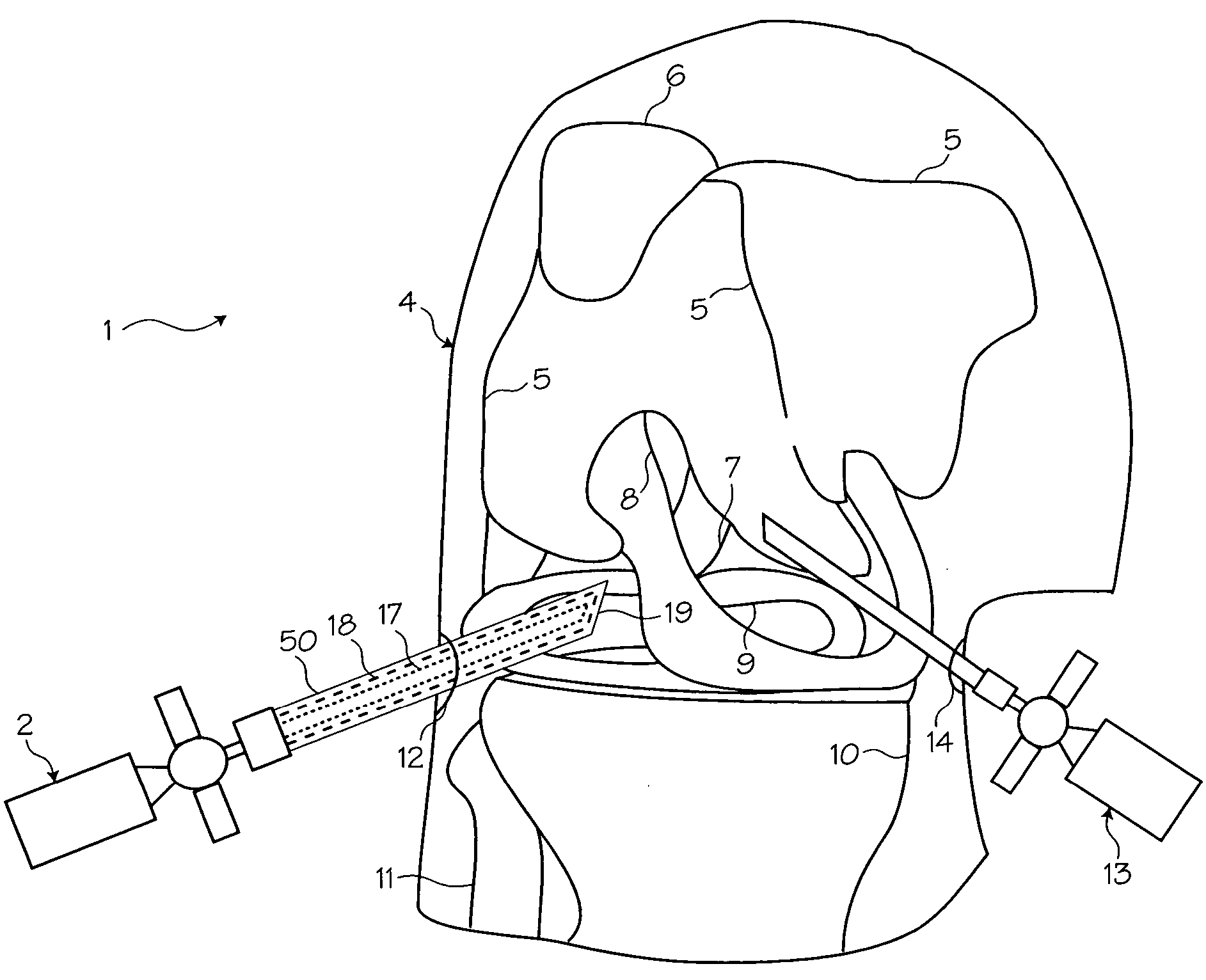
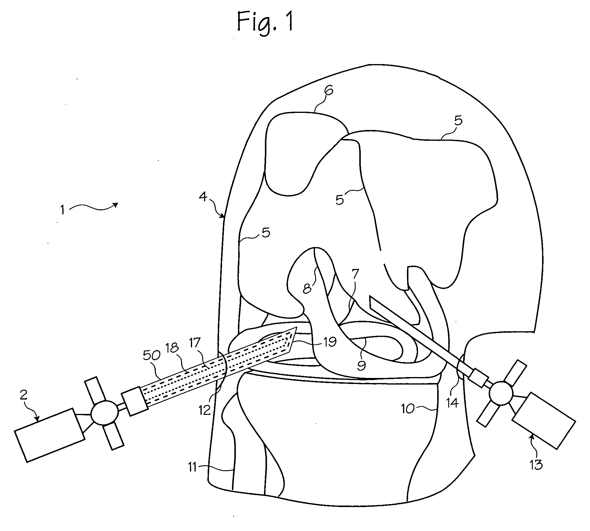
[0036]FIG. 1 shows a method of performing arthroscopic surgery on a patient by using an arthroscopic instrument 2 sheathed in an atraumatic introducer sheath 3. An arthroscopic instrument may be an arthroscope, endoscope, awl, pick, shaver, etc. In FIG. 1, the arthroscopic instrument 2 shown is an arthroscope. (The various parts of the arthroscope are shown in phantom to indicate their positions inside the sheath.) Various anatomical landmarks in the patient's knee 4 are shown for reference, including the femur 5, patella 6, posterior cruciate ligament 7, anterior cruciate ligament 8, meniscus 9, tibia 10 and fibula 11. During surgery, the surgeon introduces the arthroscope 2 into the knee via a first incision 12 in order to visualize the surgical field. A trimming instrument 13 is introduced through a second incision 14 to remove or trim tissue that the surgeon determines should be removed or trimmed. Optionally, an irrigating instrument 15 may be introduced through a third incisio...


PUM


Abstract

An arthroscopic inflow and outflow sheath providing an improved inflow and outflow system reducing the diameter of a continuous flow system while eliminating the need for a third portal during arthroscopy. The improved arthroscopic inflow and outflow sheath comprises an elongated atraumatic sheath having an inner surface, outer surface, proximal end, and distal end. The atraumatic sheath further comprises plurality of ribs or webs extending from the inner surface of the sheath and designed to contact an outer surface of the arthroscope creating outer lumens facilitating the inflow and outflow of fluid to a surgical site.

Description

[0001] This application is a continuation-in-part of U.S. application Ser. No. 10 / 769,629 filed Jan. 29, 2004.FIELD OF THE INVENTIONS [0002] The inventions described below relate the field of arthroscopic surgical instruments. BACKGROUND OF THE INVENTIONS [0003] Medical science has long sought ways to minimize the dangers and trauma inherent in invasive surgical procedures. To this end, surgical techniques and instruments have been developed which, among other things, reduce the size and number of the incisions required to perform various surgical procedures. These techniques and instruments have been remarkably successful. Procedures that only a few years ago would require multiple incisions several inches in length, are today being performed with just a few one-ince incisions. [0004] During minimally evasive surgeries, surgical instruments such as trocars, cannulas, and optical medical devices, including endoscopes, cystoscopes, arthroscopes, laparoscopes, etc., are inserted throu...

Claims


Application Information

Patent Timeline
15 Sep 2005
Publication
US20050203342A1
IPC
A61B17/34; A61M1/00; A61M25/06
CPC
A61B2017/349; A61M1/0084; A61M25/0662; A61B2217/007; A61B2017/00336; A61B2217/005; A61B17/00234; A61B1/00094
Inventors
KUCKLICK, THEODORE R.; TRIEB, MARTIN