Wire marker

Inactive Publication Date: 2005-09-22
DELPHI TECH INC
View PDF17 Cites 11 Cited by
  • Summary
  • Abstract
  • Description
  • Claims
  • Application Information

AI Technical Summary

Benefits of technology

[0006] A wire marker for marking insulation jackets of a plurality of electric wires has a stationary structure for supporting a wire maker, preferably a laser marker and more preferably a carbon dioxide laser marker. The wire marker includes a tray supported on the stationary structure below the wire marker; the tray having a plurality of substantially parallel wire grooves extending in a longitudinal direction. The support member is constructed and arranged to move along the support structure in the longitudinal direction. A motor, such as a pneumatic cylinder, moves the support member in a generally vertical direction toward and away from the tray. The wire marker pre

Problems solved by technology

Each manual intervention during the manufacturing process is time consuming and can contribute toward operator error, high manufacturing costs and/or a degradation of the overall quality of the wire harness.
Unfortunately, and especially true for smaller gauge multi-stranded wire, the stripping process can lead to conductor/core damage thus prohibiting the use of more fragile smaller gauge wires in many electrical applications.
Consequently, the cost in copper for larger gauge wire is expensive, the overall bulk of the wire harness is large and weight of the wire harness is high.
Moreove

Method used


Image

  • Wire marker
  • Wire marker
  • Wire marker

Examples


Embodiment Construction

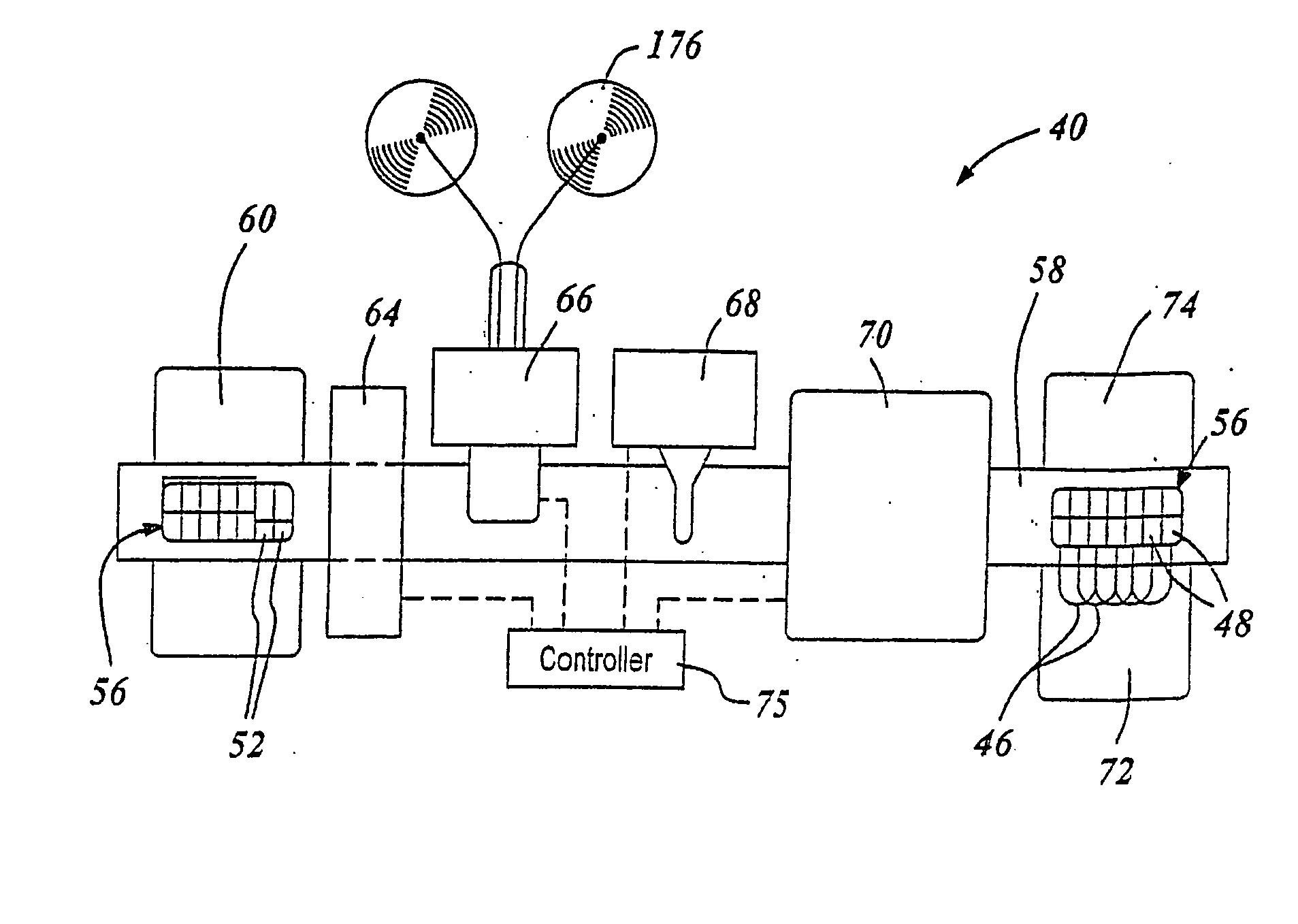
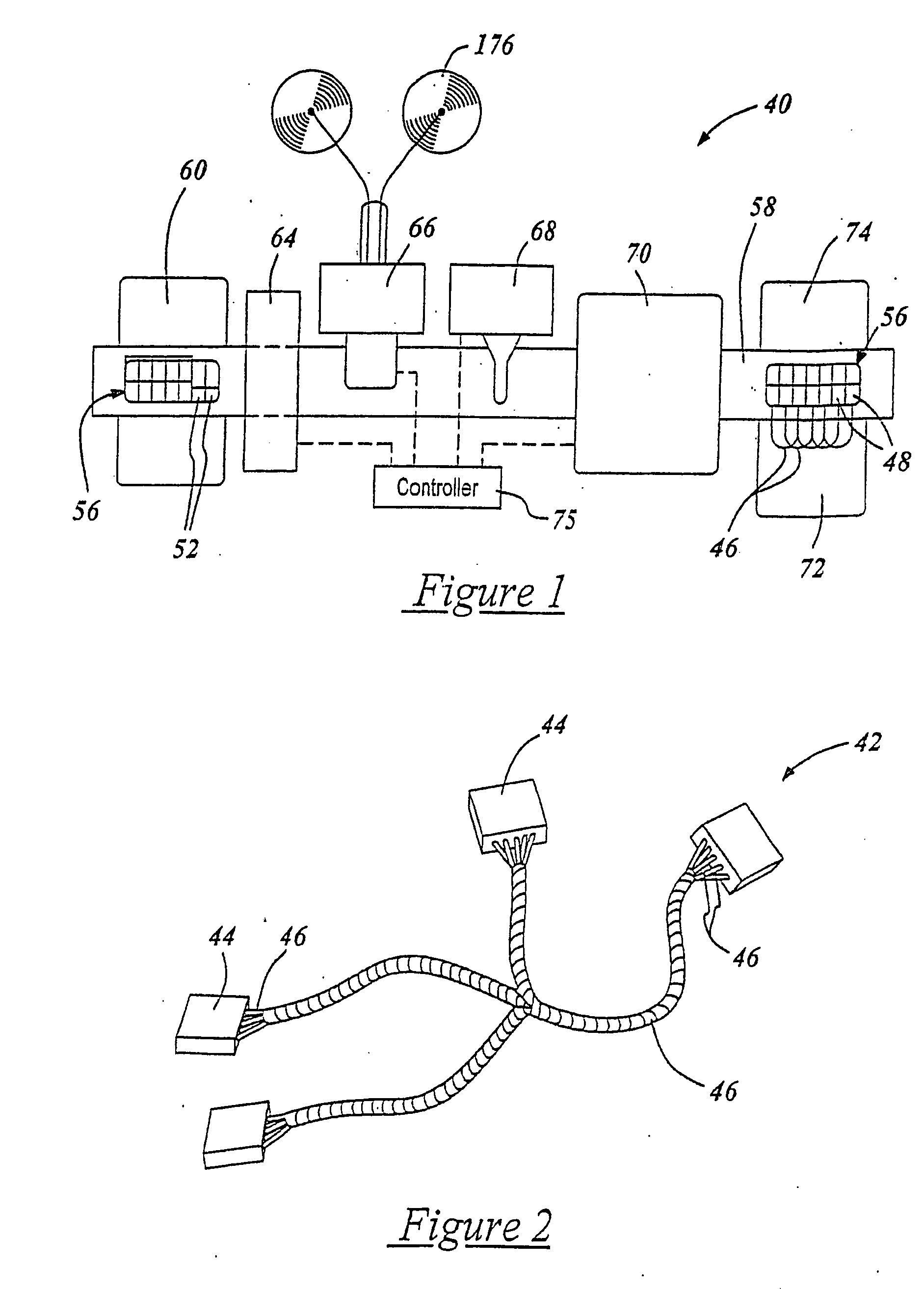
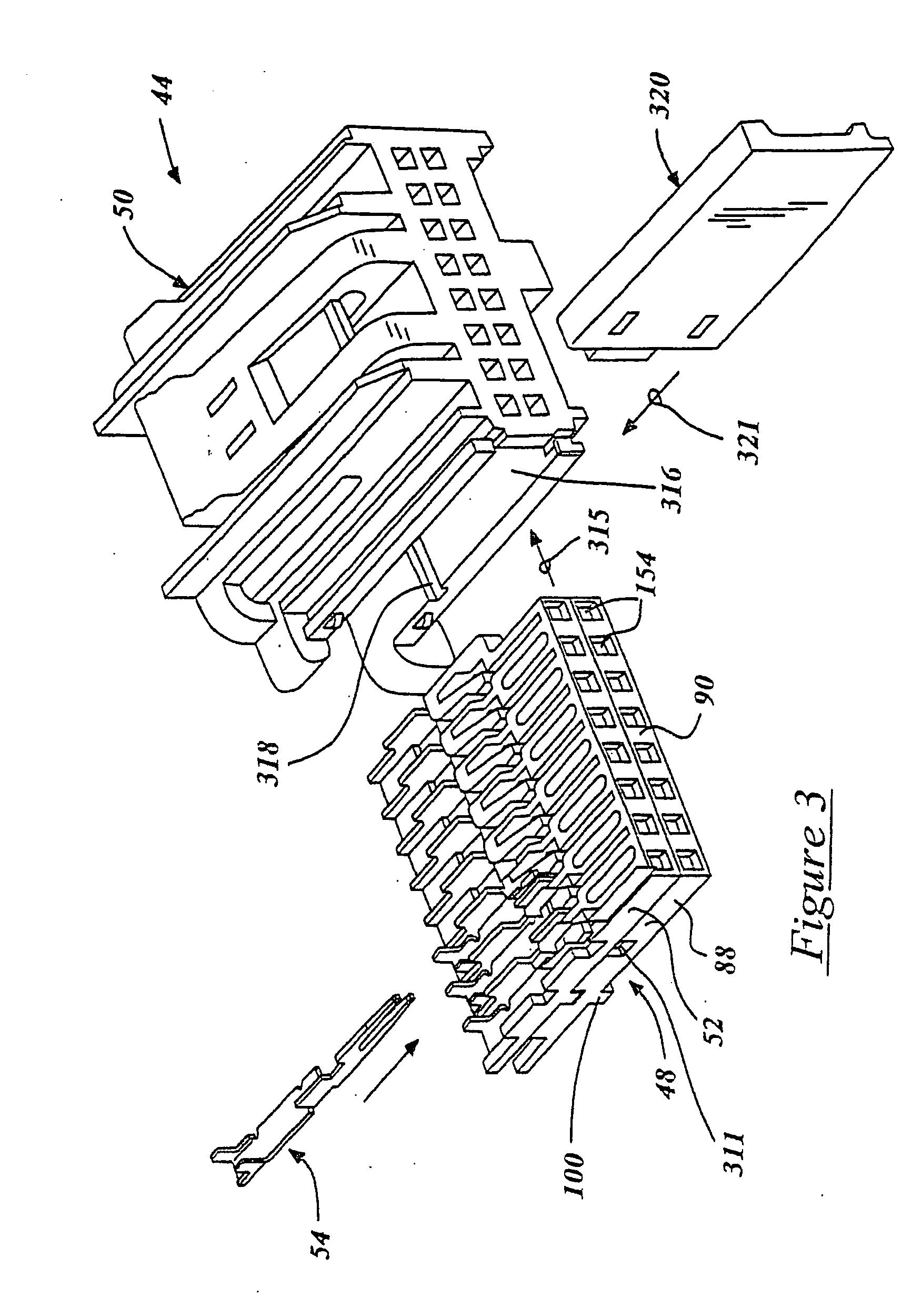
[0052] Referring to FIGS. 1-3, an automated wire harness manufacturing machine 40 of the present invention produces a novel wire harness 42, as best illustrated in FIG. 2. The wire harness 42 has a plurality of connectors 44 which are interconnected electrically to one another by a series of bundled electrically insulated wires 46. Each connector 44 has plurality of wafer assemblies 48 which are stacked and indexed to one-another within a connector housing 50. An electrical insulating wafer 52 of each wafer assembly 48 houses and locks to a plurality of terminals 54 which are spaced apart and aligned side-by-side to one another via the wafer. The wafers 52 have electrically insulating properties and are preferably made of injection molded plastic. Generally, one end of at least one insulated wire 46 is terminated to a respective terminal 54 of the wafer assembly 48 of a particular connector 44, and the other end of the same wire is engaged to another wafer assembly of a different co...


PUM


Abstract

An automated wire harness machine is capable of manufacturing a wire harness in an automated process. The wire harness is generally a plurality of bundled, preferably un-stripped, insulated wires. Each un-stripped end portion of each wire is preferably terminated by an electrical terminal in one of a series of electrical connectors of the wire harness. Each connector has at least one wafer which houses a plurality of terminals. The wire harness machine utilizes a pallet that holds all of the wafers of one wire harness. A conveyor transports the pallet and wafers through a series of stations which perform automated manufacturing steps. The first station is a terminal inserter which inserts and locks the terminals within pre-assigned cavities of the wafers. The next station is an automated wire loader which measures, cuts and crimps the two ends of each wire into the respective terminals of the loaded wafer assembly. A third station, or ultrasonic welder, then galls an un-stripped non-ferrous core of the crimped wire to the terminal. The pallet with the loaded wafers, crimped terminals, and terminated wires are then transported to a wire marker station which marks each wire, preferably via a laser, for identification purposes.

Description

RELATED PATENT APPLICATION [0001] This is a division of U.S. patent application Ser. No. 10 / 302,131 filed Nov. 22, 2002, which is a continuation-in-part application of U.S. patent application Ser. No. 10 / 205,245 filed Jul. 25, 2002, now U.S. Pat. No. 6,837,751 B2 issued Jan. 4, 2005, and U.S. patent application Ser. No. 09 / 993,797, filed Nov. 24, 2001, now U.S. Pat. No. 6,588,646 B2 issued Jul. 8, 2003.TECHNICAL FIELD [0002] The present invention relates to a wire marker for marking insulation jackets of a plurality of electrical wires. BACKGROUND OF THE INVENTION [0003] Electrical wire harnesses for automotive and other applications are assembled primarily through the use of manual labor. Areas of production which contribute toward an appreciable degree of manual intervention include: measuring and cutting predetermined wire lengths, stripping of insulation jackets from each end of the cut wire, crimping a terminal to the insulation jacket near the stripped end of the wire, electri...

Claims


Application Information

Patent Timeline
IPC IPC(8): B23K20/10B23K37/047B23K101/38B23P19/00G08B1/00H01B7/00H01B13/012H01B13/34H01R4/02H01R13/436H01R13/46H01R43/02H01R43/042H01R43/052H01R43/055H01R43/20H01R43/28H02G1/14
CPCB23K20/10Y10T29/53217B23K2201/32B23K2201/34B23K2201/38H01R4/023H01R13/436H01R13/465H01R43/0207H01R43/0228H01R43/052H01R43/055H01R43/20H01R43/28Y10T29/49192Y10T29/49179Y10T29/53209Y10T29/5327Y10T29/4919Y10T29/53213Y10T29/532Y10T29/53243Y10T29/53261Y10T29/49174Y10T29/53226Y10T29/53235Y10T29/49117Y10T29/5187Y10T29/49181Y10T29/5193B23K37/047B23K2101/32B23K2101/34B23K2101/38
Inventor GOURASH, JAMES A.KIGHTLINGER, JOHN THOMASLOPRIRE, NICK M.MCFALL, ROBERT ALANMCLANE, JOHN C.RODONDI, ANDREW F.
Owner DELPHI TECH INC
Why Eureka
Try Eureka