Exhaust heat recovery system

a heat recovery system and exhaust heat technology, applied in the direction of indirect heat exchangers, machines/engines, lighting and heating apparatus, etc., can solve the problems of energy waste, complicated configuration of exhaust heat recovery systems, and long time to complete catalyst heating, so as to improve the electric power generation and improve the efficiency of the thermoelectric conversion elemen

Inactive Publication Date: 2005-09-22
TOYOTA JIDOSHA KK
View PDF4 Cites 48 Cited by
  • Summary
  • Abstract
  • Description
  • Claims
  • Application Information

AI Technical Summary

Problems solved by technology

Accordingly, if the exhaust gas is simply discharged, the energy is wasted.
Therefore, there is a problem that it takes a long time to complete warming...

Method used


Image

  • Exhaust heat recovery system
  • Exhaust heat recovery system
  • Exhaust heat recovery system

Examples


first embodiment

[0036] Hereinafter, exemplary embodiments of the invention will be described with reference to the drawings. The same elements are denoted by the same reference numerals, and duplicate description thereof may be omitted. First, the invention will be described.

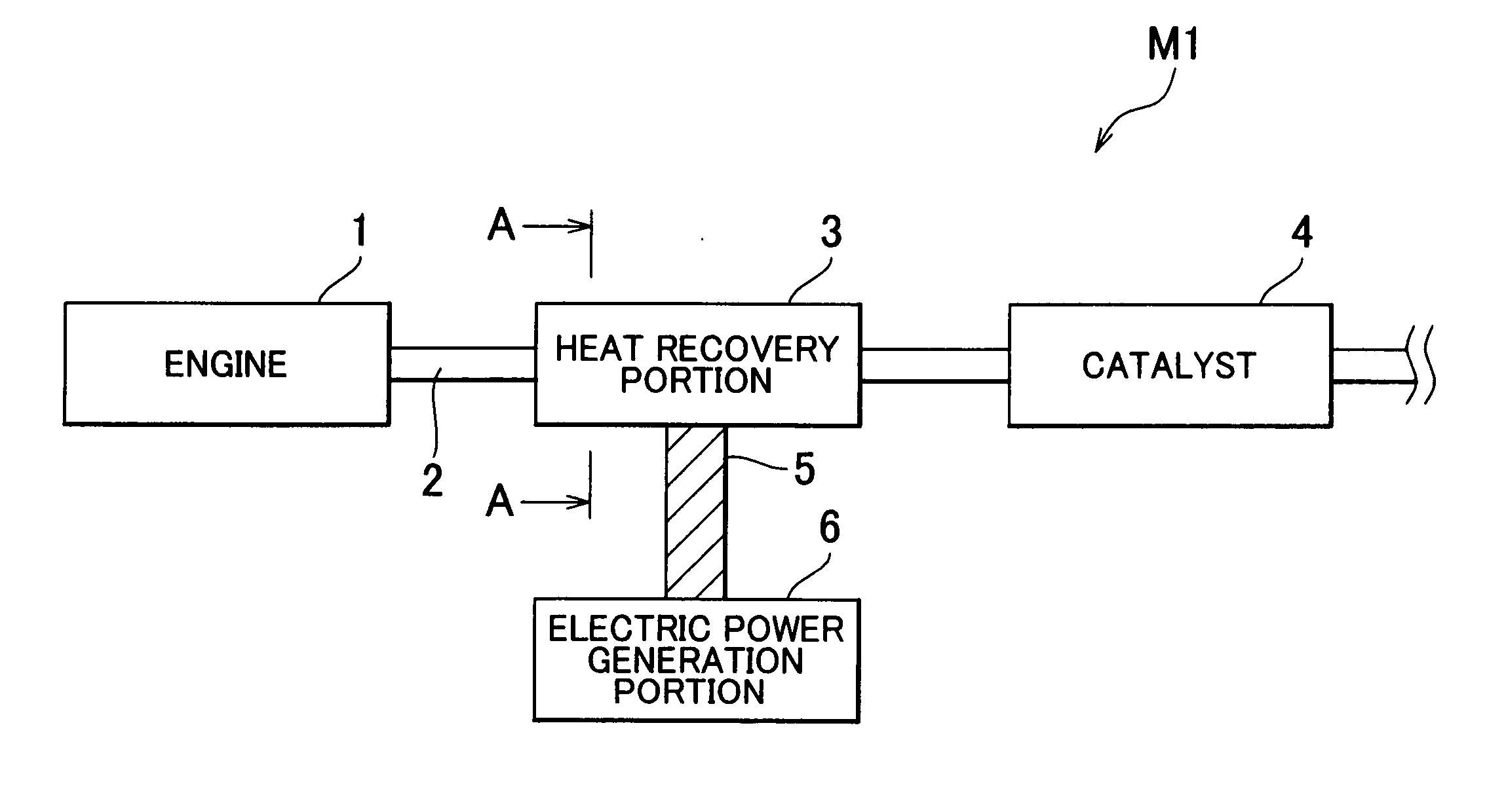
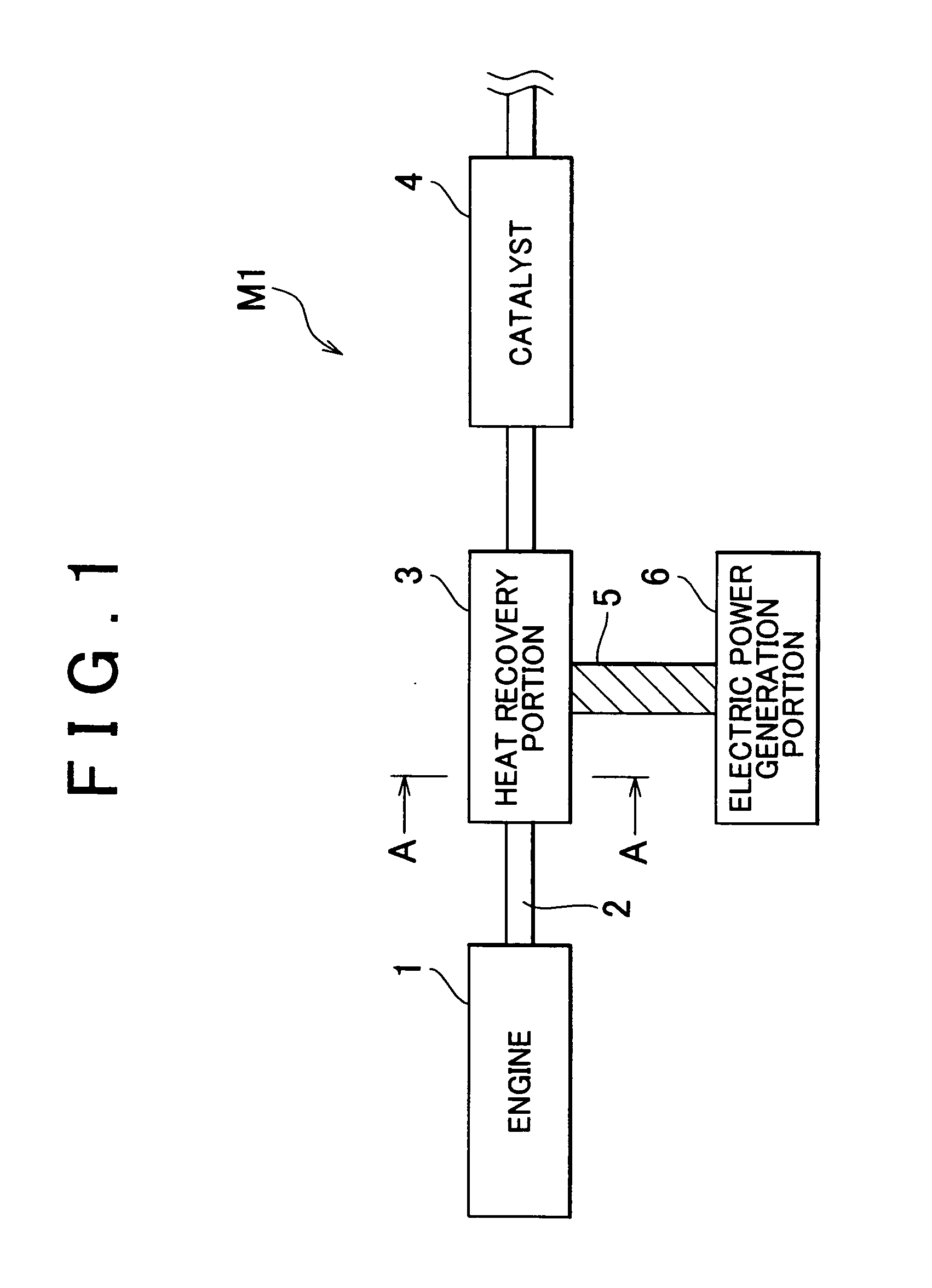
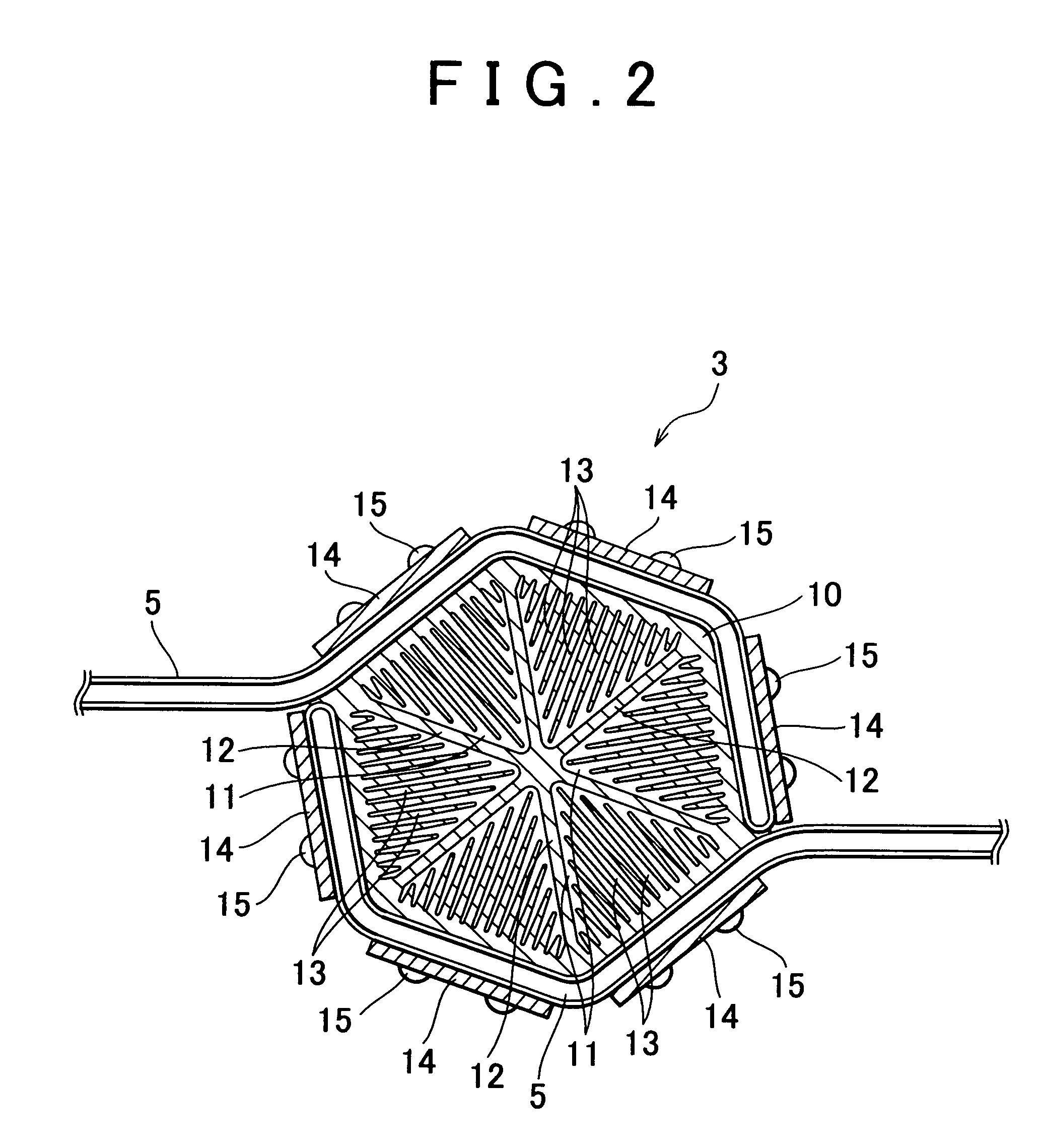
[0037]FIG. 1 is a diagram showing a configuration of an exhaust heat recovery system according to a first embodiment of the invention. FIG. 2 is a cross sectional view taken along line A-A in FIG. 1. FIG. 3 is a cross sectional view of an electric power generation portion.

[0038] As shown in FIG. 1, an exhaust heat recovery system MI according to the first embodiment includes an engine 1 which is an internal combustion engine serving as a heat source, and an exhaust pipe 2 which is connected to a muffler (not shown). Exhaust gas discharged from the engine 1 flows in the exhaust pipe 2. A heat recovery portion 3 and a catalyst 4 are provided in the exhaust pipe 2. The heat recovery portion 3 and the catalyst 4 are provided in th...

fourth embodiment

[0089] In the invention, the thermoelectric conversion 0module is not provided. However, for example, the thermoelectric conversion module may be provided downstream of the heat recovery portion 3 in the exhaust pipe 2 in the direction in which the exhaust gas flows.

[0090] In this case, the thermoelectric conversion module does not generate electric power until warming-up of the catalyst 4 is completed. Therefore, electric power generation by the thermoelectric conversion module does not prevent warming-up of the catalyst 4 from being completed early. Further, after warming-up of the catalyst 4 is completed, the heat transported to the heat recovery portion 3 from the catalyst 4 through the heat pipe 40 can be used for electric power generation performed by the thermoelectric conversion module. Also, the same effect can be obtained by connecting the thermoelectric conversion module to the heat recovery portion 3 through the heat pipe whose operation starting temperature is higher th...


PUM


Abstract

In an exhaust heat recovery system, electric power generation efficiency of a thermoelectric conversion element can be improved, and warming-up of a catalyst can be completed early, without using a complicated device. The exhaust heat recovery system according to the invention includes an exhaust pipe in which exhaust gas discharged from an internal combustion engine flows; a catalyst which purifies the exhaust gas; a heat recovery portion which is fitted to the exhaust pipe, and which recovers heat contained in the exhaust gas; a thermoelectric conversion element which generates electric power using thermoelectric conversion; and a heat pipe which connects the heat recovery portion to the thermoelectric conversion element, and which transfers the heat recovered in the heat recovery portion to the thermoelectric conversion element. An operation starting temperature of the heat pipe is set so as to be higher than an activation temperature of the catalyst.

Description

INCORPORATION BY REFERENCE [0001] The disclosure of Japanese Patent Application No. 2004-083049 filed on Mar. 22, 2004, including the specification, drawings and abstract is incorporated herein by reference in its entirety. BACKGROUND OF THE INVENTION [0002] 1. Field of the Invention [0003] The invention relates to an exhaust heat recovery system which is used in an automobile such as a hybrid vehicle, and which recovers heat energy contained in gas so as to convert the heat energy contained in the gas to electric energy. [0004] 2. Description of the Related Art [0005] Heat energy is contained in exhaust gas, and the like, that is discharged from an engine of an automobile. Accordingly, if the exhaust gas is simply discharged, the energy is wasted. To address this concern, technologies have been developed that utilize an exhaust heat recovery system to recover the heat energy contained in exhaust gas, and convert it to electric energy using a thermoelectric conversion element. The c...

Claims


Application Information

Patent Timeline
IPC IPC(8): F01N3/00F01N3/02F01N3/20F01N3/24F01N5/02
CPCF01N3/2013F01N5/025F28D15/0266F28D15/0275Y02T10/26F28F1/12H01L35/30Y02T10/16F28D21/0003Y02T10/12H10N10/13
Inventor SASAKI, TOSHITAKE
Owner TOYOTA JIDOSHA KK
Why Eureka
Try Eureka