
Use of electromagnetic acoustic transducers in downhole cement evaluation

a technology of electromagnetic acoustic transducers and cement evaluation, which is applied in the direction of survey, rotary stirring mixers, borehole/well accessories, etc., can solve the problems of affecting the efficacy of bonding logs with piezoelectric devices, limiting the variant waveforms produced by these devices, and affecting the efficacy of bonding logs

Active Publication Date: 2005-09-22
BAKER HUGHES INC
View PDF12 Cites 71 Cited by
  • Summary
  • Abstract
  • Description
  • Claims
  • Application Information

AI Technical Summary

Benefits of technology

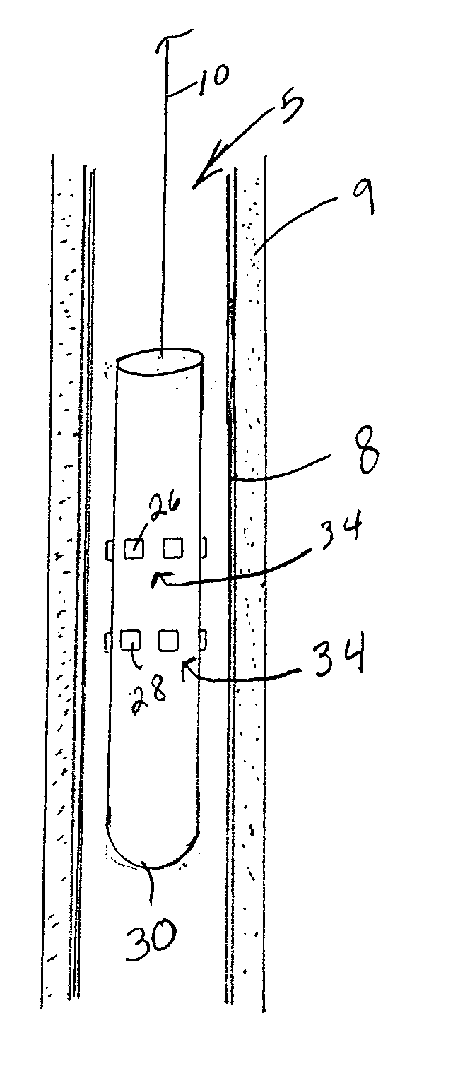
[0018] Accordingly, one of the advantages provided by the present invention is the ability to conduct casing bond logging activities in casing irrespective of the type of fluid within the casing and irrespective of the conditions of the inner surface of the casing. An additional advantage of the present invention is the ability to induce numerous waveforms within the casing, combinations of waveforms within the casing, and simultaneous waveforms within the casing.
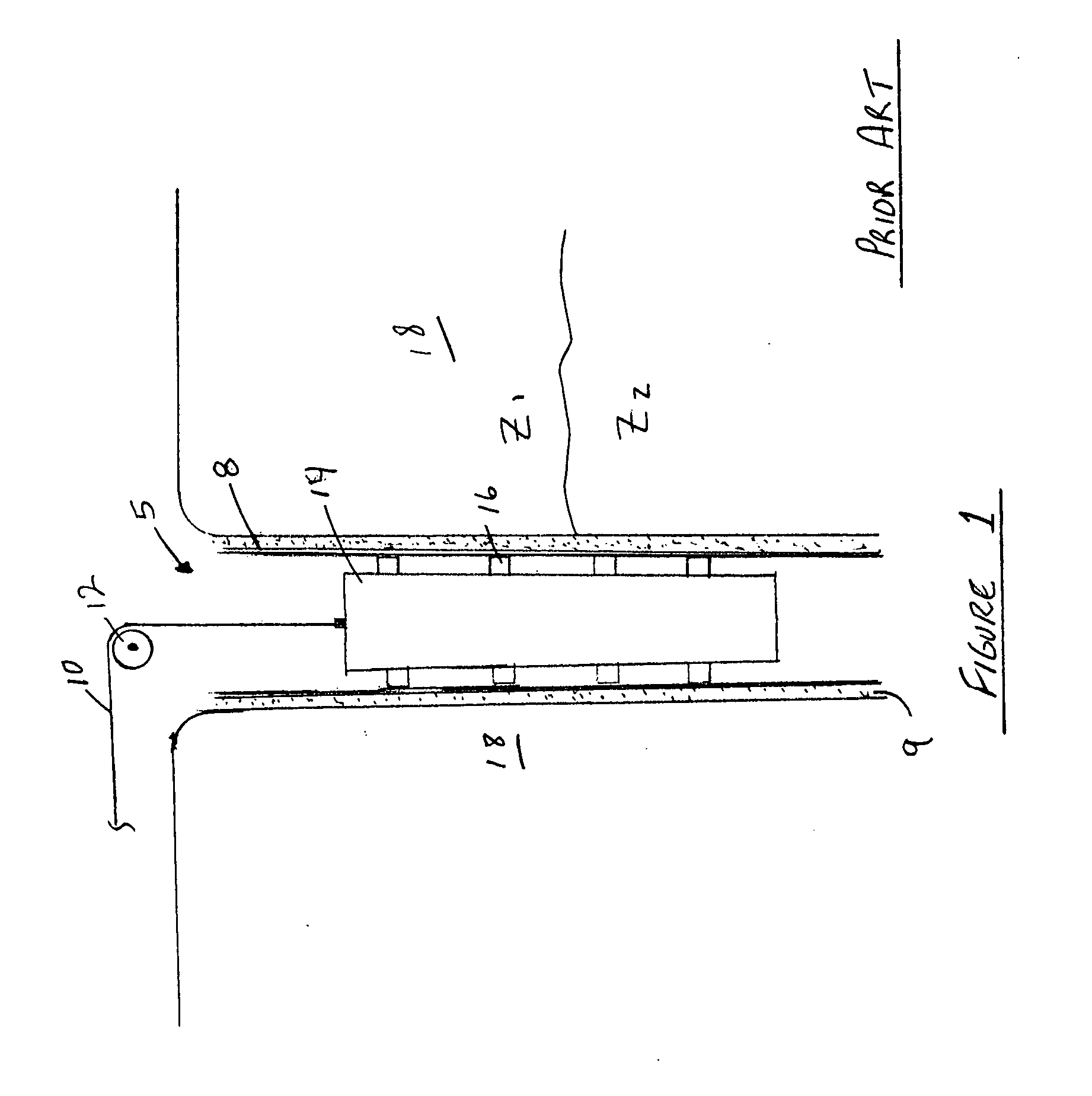
[0019]FIG. 1 depicts a partial cross section of prior art downhole cement bond log tool disposed within a wellbore.
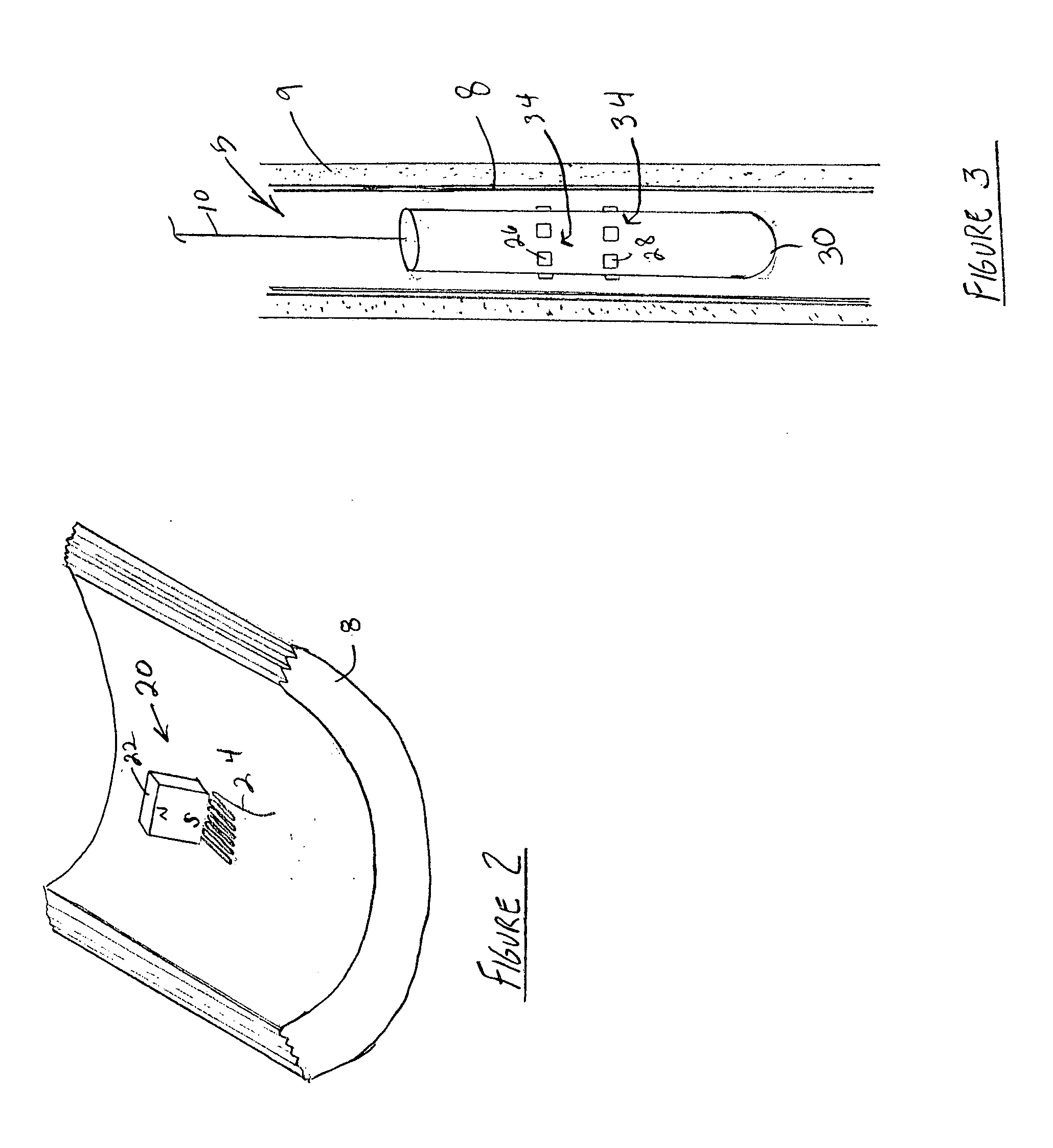
[0020]FIG. 2 illustrates a magnetic coupling transmitter disposed proximate to a section of casing.
[0021]FIG. 3 shows one embodiment of the present invention disposed within a wellbore.
[0023]FIG. 5 illustrates a compressional wave waveform along with a shear wave waveform propagating through a section of wave medium.

Problems solved by technology

Yet, lower density fluids such as gas or air and high viscosity fluids such as some drilling muds cannot provide adequate coupling between a piezoelectric device and the casing 8.
Furthermore, the presence of sludge, scale, or other like matter on the inner circumference of the casing 8 can detrimentally affect the efficacy of a bond log with a piezoelectric device.
Another drawback faced when employing piezoelectric devices for use in bond logging operations involves the limitation of variant waveforms produced by these devices.
Application of these devices is limited to conducting an evaluation of only the wellbore casing itself.

Method used


Image

  • Use of electromagnetic acoustic transducers in downhole cement evaluation
  • Use of electromagnetic acoustic transducers in downhole cement evaluation
  • Use of electromagnetic acoustic transducers in downhole cement evaluation

Examples


Embodiment Construction

[0024] With reference to the drawing herein, one embodiment of a magnetically coupled transducer 20 proximate to a section of casing 8 is depicted in FIG. 2. For the purposes of clarity, only a portion of the length and diameter of a section of casing 8 is illustrated and the magnetically coupled transducer 20 is shown in exploded view. It is preferred that the magnetically coupled transducer 20 be positioned within the inner circumference of the tubular casing 8, but as is noted below, the magnetically coupled transducer 20 can be positioned in other areas.

[0025] In the embodiment of the present invention shown in FIG. 2, the magnetically coupled transducer 20 is comprised of a magnet 22 and a coil 24, where the coil 24 is positioned between the magnet 22 and the inner circumference of the casing 8. An electrical current source (not shown) is connectable to the coil 24 capable of providing electrical current to the coil 24. The magnet 22, while shown as a permanent magnet, can als...


PUM


Abstract

A bond log device comprising a sonde, an acoustic transducer, and an acoustic receiver. The acoustic transducer is comprised of a magnet combined with a coil, where the coil is energizable by an electrical current source. The acoustic transducer can also be comprised of an electromagnetic acoustic device. The acoustic transducer is capable of producing various waveforms, including compressional waves, shear waves, transversely polarized shear waves, Rayleigh waves, Lamb waves, and combinations thereof.

Description

BACKGROUND OF THE INVENTION [0001] 1. Field of the Invention [0002] The invention relates generally to the field of the evaluation of wellbore casing. More specifically, the present invention relates to a method and apparatus to provide for the analysis of the bond that secures casing within a wellbore. Yet even more specifically, the present invention relates to a method and apparatus that enables non-destructive testing of the bond securing casing within a wellbore where the testing includes the production and transmitting of multiple waveforms including compressional waves, shear waves, Lamb waves, Rayleigh waves, and combinations thereof, in addition to the receiving and recording of the waveforms within the casing. [0003] 2. Description of Related Art [0004] Hydrocarbon producing wellbores typically comprise casing 8 set within the wellbore 5, where the casing 8 is bonded to the wellbore by adding cement 9 within the annulus formed between the outer diameter of the casing 8 and...

Claims


Application Information

Patent Timeline
Patent Type & Authority Applications(United States)
IPC IPC(8): E21B1/00E21B23/00E21B47/00E21B47/16
CPCE21B47/16E21B47/0005E21B47/005
Inventor BAROLAK, JOSEPHBOLSHAKOV, ALEXEIDUBINSKY, VLADIMIRPATTERSON, DOUGLAS
Owner BAKER HUGHES INC
Learn More