

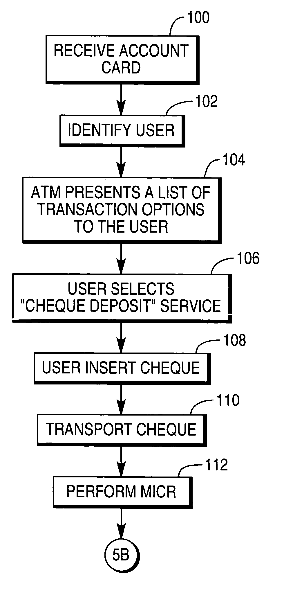
Cheque deposit at a self-service terminal
- Summary
- Abstract
- Description
- Claims
- Application Information
AI Technical Summary
Benefits of technology
Problems solved by technology
Method used
Image

Examples
Embodiment Construction
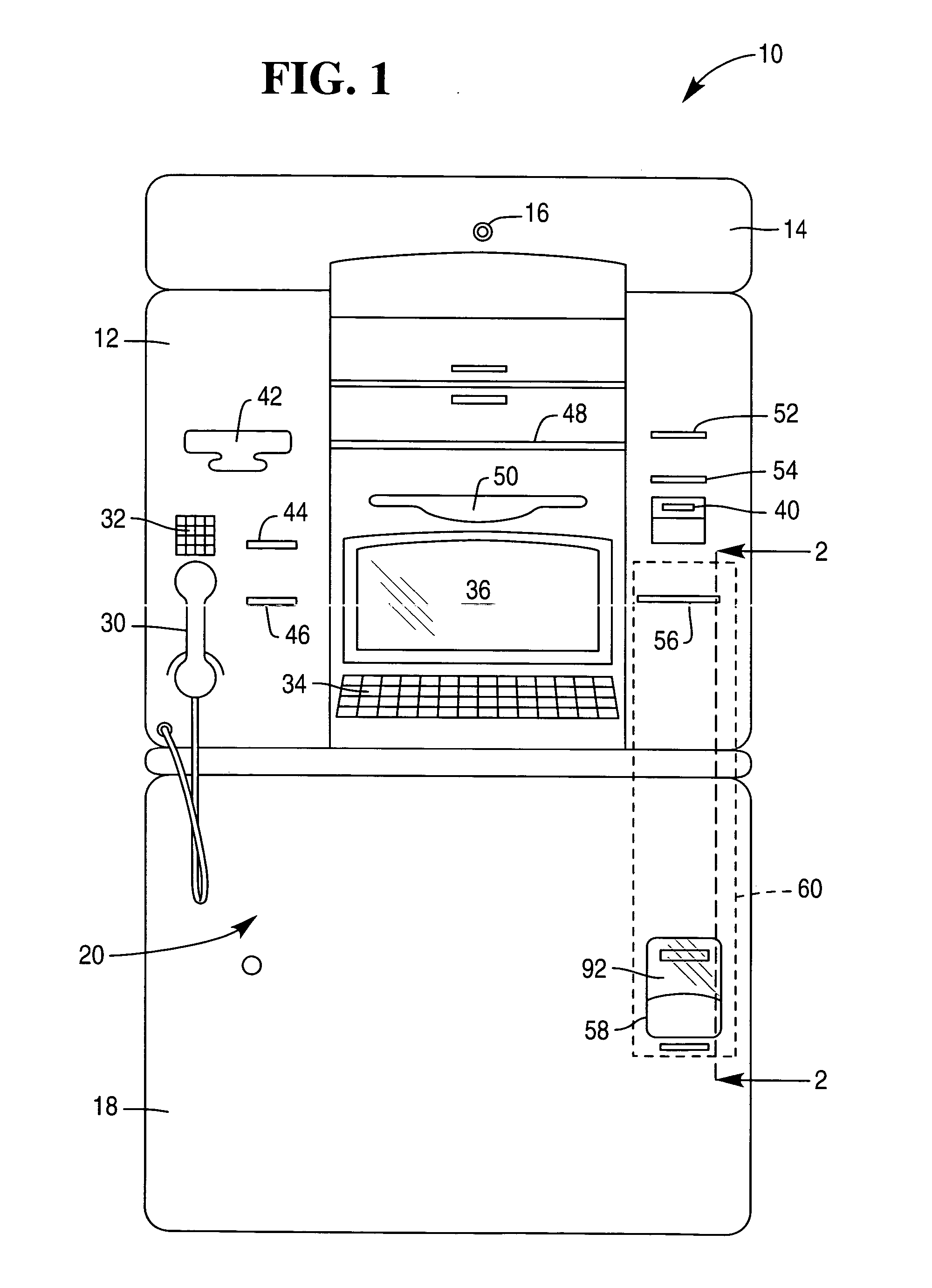
[0028] Reference is first made to FIG. 1, which illustrates a self-service terminal 10 in the form of a cheque deposit / cashing ATM. The ATM 10 comprises a fascia 12 pivotably coupled to a chassis (not shown); an upper panel 14 mounted to the chassis and defining an aperture 16 through which a camera (not shown) images a user of the ATM 10; and a lower panel 18 hingeably coupled to the chassis (not shown) so that the lower panel 18 can be opened to reveal a safe (not shown) mounted in the chassis (not shown).
[0029] When the lower panel 18 is open, the fascia 12 can be pivoted upwards to reveal ATM modules mounted within the chassis (not shown).
[0030] The fascia 12 and lower panel 18 provide a user interface 20 for allowing a user to execute a transaction. The fascia 12 includes a handset 30 and a telephone keypad 32 for allowing a user to contact a remote operator (not shown) typically located in a call centre (not shown). The fascia 12 also includes an encrypting keyboard 34 for a...
PUM
 Abstract
Description
Claims
Application Information