HVAC system with powered subcooler

a subcooler and hvac technology, applied in the field of hvac systems, can solve the problems of limited compressor efficiency, compressor loss, general inability to fully realize the theoretical benefit of the economizer cycle, etc., and achieve the effects of increasing efficiency, increasing efficiency, and increasing capacity

Active Publication Date: 2011-03-22
JOHNSON CONTROLS TYCO IP HLDG LLP
View PDF39 Cites 21 Cited by
  • Summary
  • Abstract
  • Description
  • Claims
  • Application Information

AI Technical Summary

Benefits of technology

[0011]An advantage of the present invention is that the system has a larger capacity than is available with conventional economizer cycles, and operates at an increased efficiency with respect to conventional economizer cycles.
[0012]A further advantage of the present invention is that the additional efficiency and capacity can be provided without complicated equipment or wiring, allowing the system to be manufactured at a relatively low cost. The powered subcooler circuit includes a design having equipment that is readily available and is easily manufactured. In addition, the increased cooling capacity of the system of the present invention offsets at least a portion of the cost of the additional equipment.
[0013]Yet another advantage of the present system is that the addition of powered subcooler systems according to the present invention permits the use of smaller condenser coils, while providing increased cooling capacity.
[0014]Another advantage of the present system is that the system may operate at high ambient temperatures, including temperatures that exceed 95° F. (35° C.).
[0015]Still another advantage of the present invention is that the system operates with a reduced fan noise at the same capacity, as compared to a convention chiller system. The reduced fan noise results because the required size of the condenser and the number of fans / fan capacity is smaller, therefore reducing the fan noise produced by the condenser.
[0016]Still yet another advantage of the present invention is that the system is able to provide additional stepped control of subcooler capacity when ambient conditions change. Each of the subcooler circuits provides a predetermined amount of subcooling. Therefore, activating and deactivating the individual subcooling circuits in response to subcooling requirements permits the system to operate with less energy costs.

Problems solved by technology

The introduction of moderate pressure refrigerant gas improves the efficiency of the thermodynamic cycle in spite of limited compressor efficiency.
Another limitation is that these approaches require a special port to the compressor to allow the introduction of intermediate pressure gas.
Additional compressor losses associated with this port generally do not allow the full theoretical benefit of the economizer cycle.
Powered subcoolers have seen limited use in low-temperature refrigeration systems, such as in supermarket refrigerators and / or freezers.
), which would introduce a substantial performance penalty in air conditioning systems.
In addition, the prior art teaches the use of separate condensers for the main circuit and subcooler circuit, which increases the space requirements for the system.
), the issues with operation near or above the critical temperature are even greater.
As the refrigerant reaches or exceeds its critical temperature, the condenser loses the ability to condense the refrigerant, leading to efficiency and capacity losses and / or system failures during times of high outdoor ambient temperature.

Method used


Image

  • HVAC system with powered subcooler
  • HVAC system with powered subcooler
  • HVAC system with powered subcooler

Examples


examples

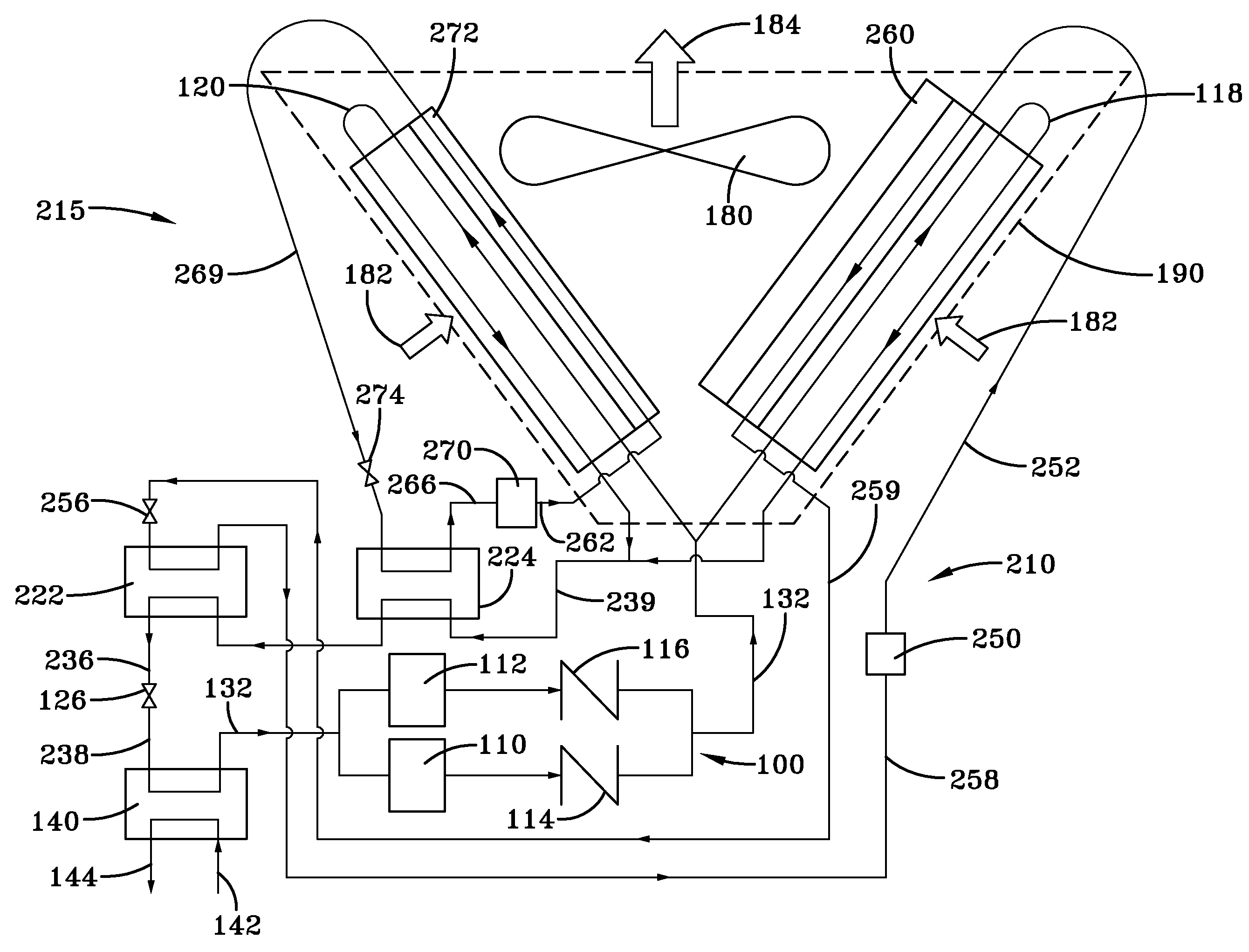
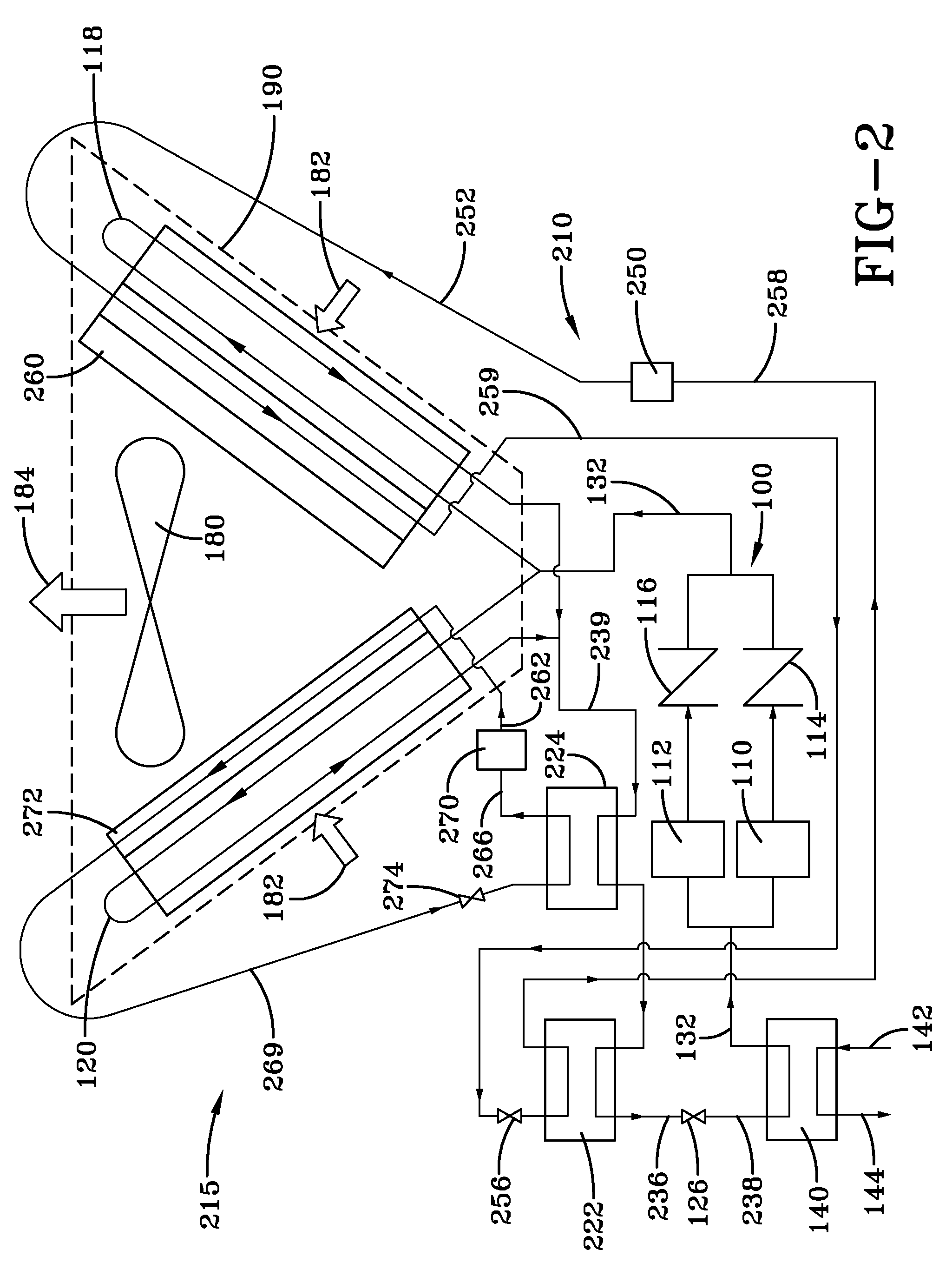
[0046]Table 1 below includes the conditions for an air-cooled chiller according to an embodiment of the present invention. In this embodiment, the system cools refrigerant liquid in the main circuit 100 from about 105° F. (41° C.) to about 60° F. (16° C.) using two steps. The two steps correspond to the cooling that takes place in each of the first and second subcoolers 222 and 224. Refrigerant in the second subcooler circuit 215 is evaporated in second subcooler 224. The evaporating refrigerant in the second subcooler 224 exchanges heat with the main circuit 100. The heat exchange results in a temperature of the liquid refrigerant leaving the second subcooler 224 of about 78.5° F. (26° C.). The evaporating refrigerant in the first subcooler 222 exchanges heat with the main circuit 100. The heat exchange results in a temperature of the liquid refrigerant leaving the first subcooler 222 of about 60° F. (16° C.). The refrigerant, which has a temperature of about 60° F., is then transp...


PUM


Abstract

An HVAC system having a main circuit and a subcooler circuit. The main circuit includes a main circuit evaporator, a main circuit expansion device, a main circuit condenser and a main circuit compressor connected in a closed refrigerant loop. The subcooler circuit includes a subcooler evaporator, a subcooler expansion device, a subcooler condenser and a subcooler compressor connected in a closed refrigerant loop. The subcooler evaporator is arranged and disposed to exchange heat between liquid refrigerant in the main circuit and the refrigerant in the subcooler circuit to cool the liquid refrigerant in the main circuit prior to entering the main circuit evaporator. The operation of the subcooler circuit provides an increased cooling capacity per unit of a mass flow of cooling fluid through the main circuit condenser and subcooler condenser for the HVAC system with a predetermined design efficiency.

Description

FIELD OF THE INVENTION[0001]The present invention is directed to an HVAC system. In particular, the present invention is drawn to a chiller system with a powered subcooler.BACKGROUND OF THE INVENTION[0002]Extensive development work spanning many decades has been spent in optimizing the design of commercial air conditioners.[0003]One attempt to optimize commercial air conditioners includes the installation of an economizer. Economizers have been commonly used in screw chillers. A typical economizer introduces refrigerant flash gas from an intercooler to the compressor at a pressure that is between that of the evaporator and the condenser. The introduction of moderate pressure refrigerant gas improves the efficiency of the thermodynamic cycle in spite of limited compressor efficiency. In another attempt to optimize commercial air conditioners, a heat exchanger is used to cool the refrigerant liquid leaving the condenser using refrigerant boiling at an intermediate pressure which is re...

Claims


Application Information

Patent Timeline
Patent Type & Authority Patents(United States)
IPC IPC(8): F25D17/00
CPCF25B6/02F25B7/00F25B9/008F25B40/02F25B13/00F25B2309/061F25B2313/02741F25B2339/047F25B2400/0417F25B2400/075F25B2400/23F25B2600/0251F25B2600/111F25B2700/2106Y02B30/743Y02B30/70F25B9/00
Inventor KOPKO, WILLIAM L.
Owner JOHNSON CONTROLS TYCO IP HLDG LLP
Why Eureka
Try Eureka