
Image reading apparatus

a reading apparatus and reading technology, applied in the direction of instruments, conversion screens, nuclear engineering, etc., can solve the problems of inability to eliminate curling, moisture condensation and inability to efficiently read the recorded radiation image information from the stimulable phosphor sheet in the image reading apparatus. to achieve the effect of preventing moisture condensation

Inactive Publication Date: 2005-09-22
FUJIFILM CORP +1
View PDF10 Cites 1 Cited by
  • Summary
  • Abstract
  • Description
  • Claims
  • Application Information

AI Technical Summary

Benefits of technology

[0014] It is a general object of the present invention to provide an image reading apparatus that includes a mechanism for heating the interior of the image reading apparatus, to prevent moisture condensation in the image reading apparatus, and to allow a stimulable phosphor sheet to be fed smoothly and reliably through the image reading apparatus.
[0015] According to the present invention, a heating mechanism is disposed in a casing of an image reading apparatus for heating the interior of the apparatus casing to a predetermined temperature. When the image reading apparatus is used in low temperature environments, during winter and in cold climates, the interior of the casing is heated beforehand to a predetermined temperature by the heating mechanism. Therefore, even if the temperature outside of the image reading apparatus is quickly increased, a temperature difference is prevented from being abruptly caused between the temperature outside of the image reading apparatus and the temperature inside the casing.
[0016] Consequently, moisture condensation is prevented from occurring in the casing even when the temperature outside of the image reading apparatus is increased, and there is no need to provide a dehumidifier or the like inside the casing for removing moisture condensation. Therefore, the image reading apparatus can be reduced in size and the installation space for installing the image reading apparatus therein can be reduced.
[0017] Since the interior of the casing is heated by the heating mechanism, when a stimulable phosphor sheet is introduced into the casing that has a curl at an end thereof due to low temperatures, the curl is eliminated from the stimulable phosphor sheet inside the heated casing. Consequently, the stimulable phosphor sheet can smoothly and reliably be fed in an auxiliary scanning direction inside the image reading apparatus by an auxiliary scanning feed mechanism.

Problems solved by technology

If the stimulable phosphor sheet is curled at its leading end, then the curled end cannot enter smoothly between feed rollers while the stimulable phosphor sheet is being transported through the image reading apparatus, resulting in a failure to efficiently read the recorded radiation image information from the stimulable phosphor sheet in the image reading apparatus.
When the room is heated, moisture condensation may occur in the image reading apparatus, due to a temperature difference that is abruptly caused between the temperature in the room and the temperature within the image reading apparatus.
The apparatus disclosed in Japanese Laid-Open Patent Publication No. 05-262012 and Japanese Laid-Open Patent Publication No. 2003-287866 are unable to prevent moisture condensation due to a rapid temperature rise caused by heating when the image reading apparatus is used at low temperatures during winter and in cold climates, and such apparatus are also unable to eliminate curling that may possibly occur at the end of a stimulable phosphor sheet that is fed into the image reading apparatus.
However, this solution is disadvantageous in that the image reading apparatus is increased in size due to the dehumidifier.
As a result, the recorded radiation image information cannot be read efficiently from the stimulable phosphor sheet by the image reading apparatus.

Method used


Image

  • Image reading apparatus
  • Image reading apparatus
  • Image reading apparatus

Examples


Embodiment Construction

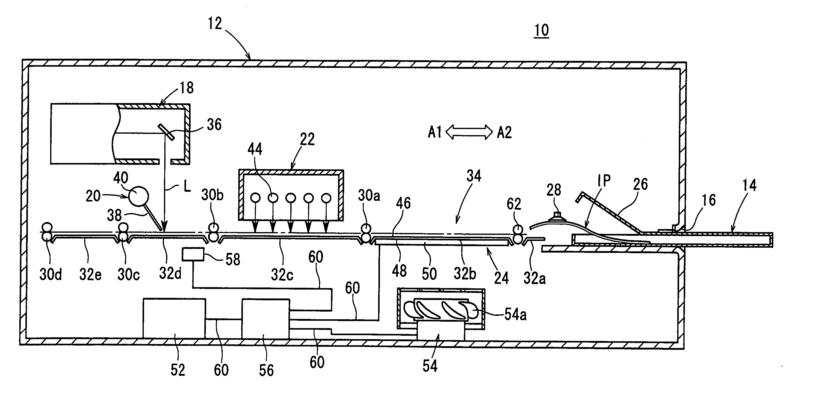
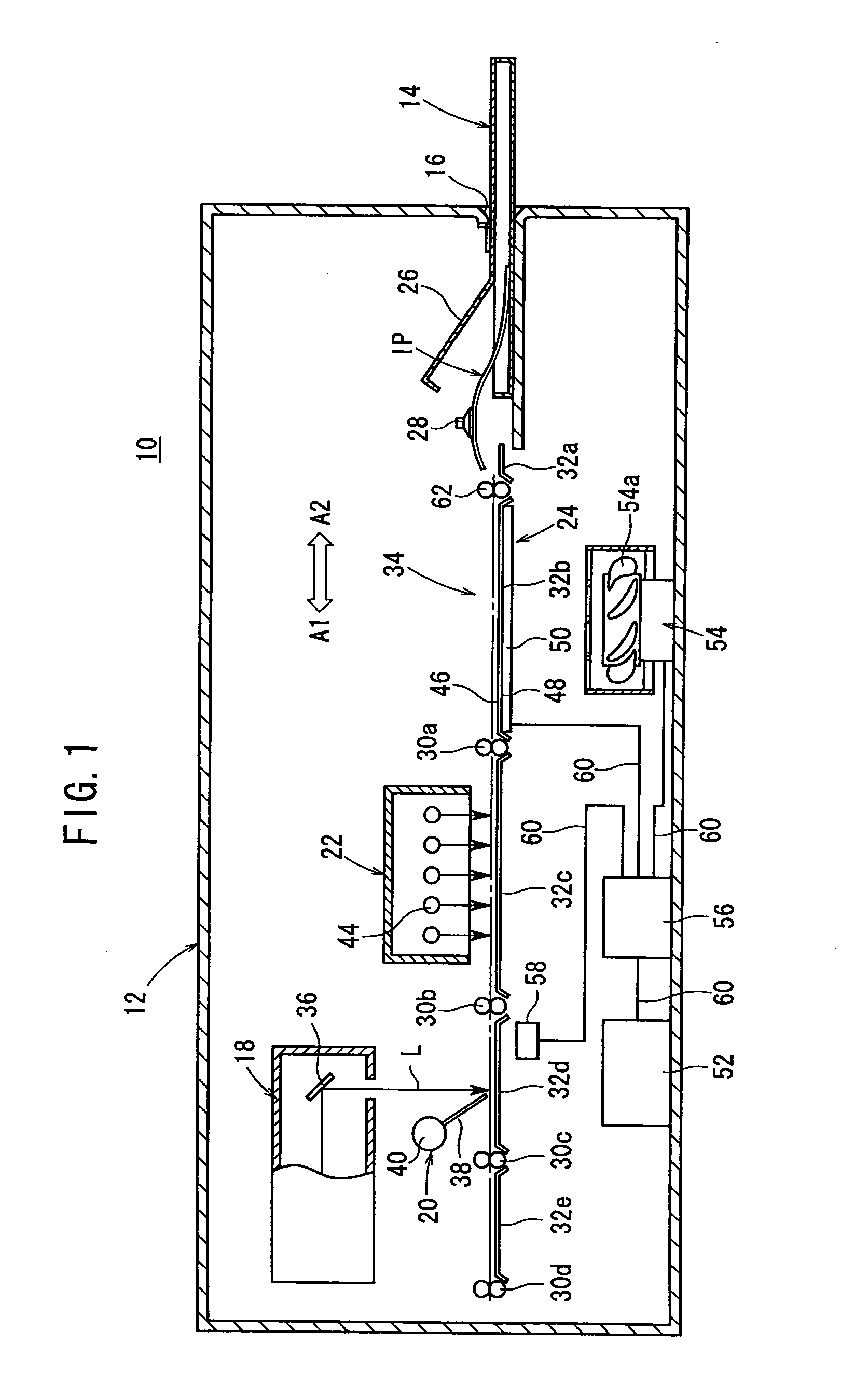
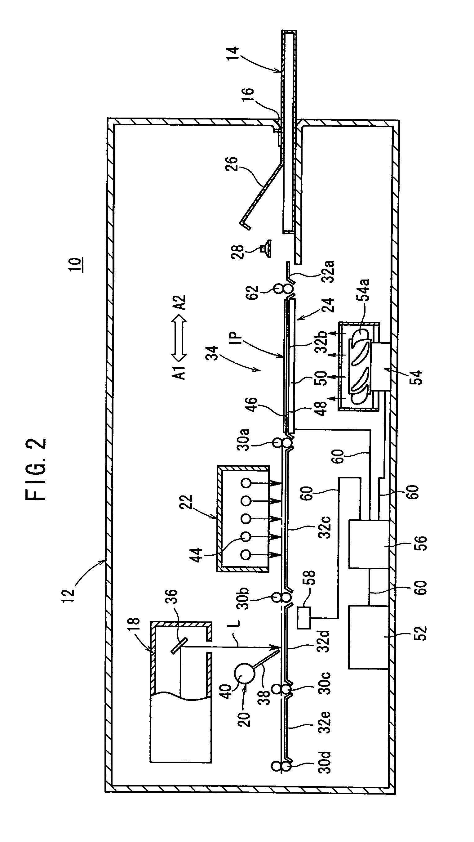
[0026]FIGS. 1 and 2 show in schematic vertical cross section an image reading apparatus 10 according to an embodiment of the present invention.

[0027] As shown in FIGS. 1 and 2, the image reading apparatus 10 has a casing 12, a cassette loader 16 disposed on an end of the casing 12 for loading therein a cassette 14, which holds a stimulable phosphor sheet IP having recorded thereon radiation image information of a subject such as a human body, a scanning unit 18 disposed in the casing 12 for applying a laser beam L as stimulating light to the stimulable phosphor sheet IP with the radiation image information recorded thereon, a reading unit (reading mechanism) 20 disposed in the casing 12 for optically reading light that is emitted from the stimulable phosphor sheet IP upon exposure to the laser beam L, an erasing unit 22 disposed in the casing 12 for erasing remaining radiation image information from the stimulable phosphor sheet IP after the emitted light is read from the stimulabl...


PUM


Abstract

An image reading apparatus includes a casing accommodating therein a heating mechanism for heating the interior of the casing. The heating mechanism has a heating body mounted on a guide plate along which a stimulable phosphor sheet is fed. When supplied with electric current, the heating body is heated to heat the guide plate to a predetermined temperature. An air blower is disposed in confronting relation to the heating body and is energized to circulate heated air inside the casing. A temperature detector detects the atmospheric temperature inside the casing, and when the detected atmospheric temperature becomes higher than a reference temperature preset in a controller, the controller stops supplying electric current to the heating body.

Description

BACKGROUND OF THE INVENTION [0001] 1. Field of the Invention [0002] The present invention relates to an image reading apparatus for reading radiation image information recorded on a stimulable phosphor sheet stored in a cassette, and thereafter erasing remaining radiation image information from the stimulable phosphor sheet. [0003] 2. Description of the Related Art [0004] There has heretofore been known a stimulable phosphor which, when exposed to applied radiation (X-rays, α-rays, β-rays, γ-rays, electron beams, ultraviolet radiation, or the like), stores part of the energy of the radiation, and, when subsequently exposed to applied stimulating rays such as visible light, emits light in proportion to the stored energy of the radiation. An image forming apparatus, which is known in the art, records radiation image information of a subject such as a human body on a stimulable phosphor sheet having a stimulable phosphor layer formed thereon. [0005] An image reading apparatus has a cas...

Claims


Application Information

Patent Timeline
Patent Type & Authority Applications(United States)
IPC IPC(8): G01T1/00G21K4/00G02B26/10G02B27/02G03B42/02H04N1/04
CPCG02B27/023
Inventor MAMIYA, AKIFUMI
Owner FUJIFILM CORP
Learn More