Cylinder head gasket

a technology of cylinder head and gasket, which is applied in the direction of engine seals, machine/engines, and engine sealing arrangements, etc., can solve the problem that the gasket clamped between the engine block and the cylinder head cannot offer a really great resistance to flattening, and achieve the effect of thickening the compressed cylinder head gask

Inactive Publication Date: 2005-09-22
ELRINGKLINGER AG
View PDF16 Cites 45 Cited by
  • Summary
  • Abstract
  • Description
  • Claims
  • Application Information

AI Technical Summary

Benefits of technology

[0015] The supporting devices in question differ, however, quite fundamentally from stoppers: Whereas a spring-elastic sealing bead to be protected by a stopper is always associated with this stopper and the stopper is located in the direct vicinity of the sealing bead and extends at least essentially over the entire length of the sealing bead and around an aperture of the gasket to be sealed, a supporting device according to the present invention has none of these features characteristic of a stopper even if a sealing bead can extend in the vicinity of a supporting device—in this case, the supporting device extends only along a section of the sealing bead which is much shorter than the overall length of the sealing bead; further, the effective height of the supporting device may be the same as or even greater than the height of the bead. Therefore, the supporting device shall not take over the function of protecting the sealing bead from any excessive flattening.
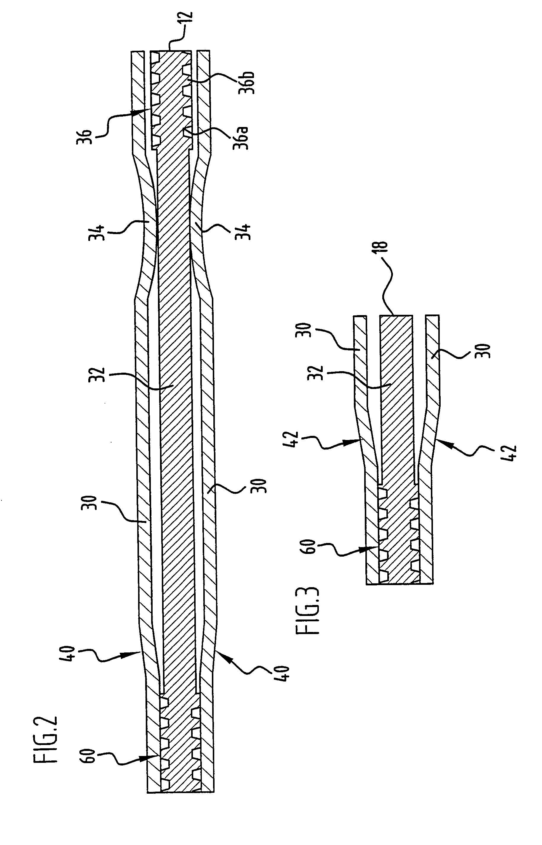
[0016] In the case of a multi-layered, inventive cylinder head gasket, the supporting device or the supporting devices can be provided in the same sheet-metal layer as the sealing device or the sealing devices or in another layer since it is, primarily, only of importance for the thickness of the compressed cylinder head gasket to be increased at the location of the supporting device. In a plan view of the cylinder head gasket, the distance of the supporting device from the sealing device located closest to it is generally, at least over a greater part of the length of this sealing device, considerably greater than the width of the sealing device (measured in a radial direction with respect to the aperture of the cylinder head gasket which is to be sealed and is associated with the sealing device), namely even when the sealing device consists of one or several sealing beads and one or several stoppers protecting them. When a greater material thickness or a greater overall thickness in the area of a supporting device is mentioned in the above, the material thickness or the thickness of the supporting device is to be understood as the distance between two tangential planes which extend parallel to the plane of the gasket plate and are tangent to the supporting device on both sides and enclose it between them. The apertures of the cylinder head gasket which are to be sealed are to be understood primarily as its combustion chamber apertures; if the cylinder head gasket does, however, have apertures for the passage of, for example, a cooling medium or of oil which are to be sealed with one or several sealing devices of the cylinder head gasket, such as is the case for, e.g., a sealing bead which extends in the vicinity of the periphery of a cylinder head gasket, forms a complete, continuous line and encloses a group of such apertures of the cylinder head gasket which have a fluid flowing through them, the definition that the thickened supporting area of an inventive supporting device does not enclose any of these apertures completely or almost completely also relates to this case. Furthermore, preferred embodiments are characterized by the fact that when the cylinder head gasket has a sealing bead adjacent to an inventive supporting area, the supporting area extends only over a smaller part of the length of the sealing bead adjacent to it, i.e., over less than half the length of this sealing bead.
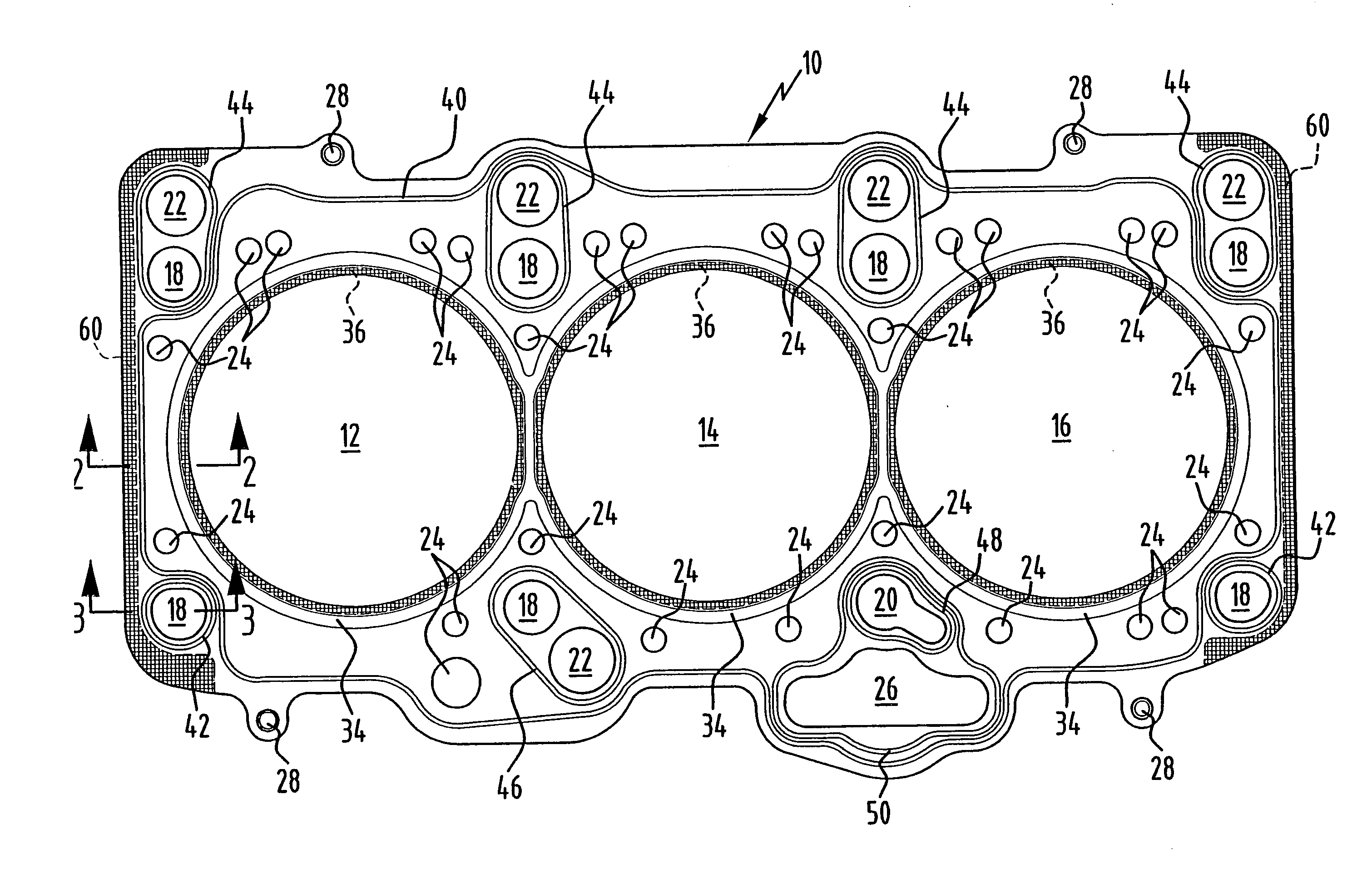
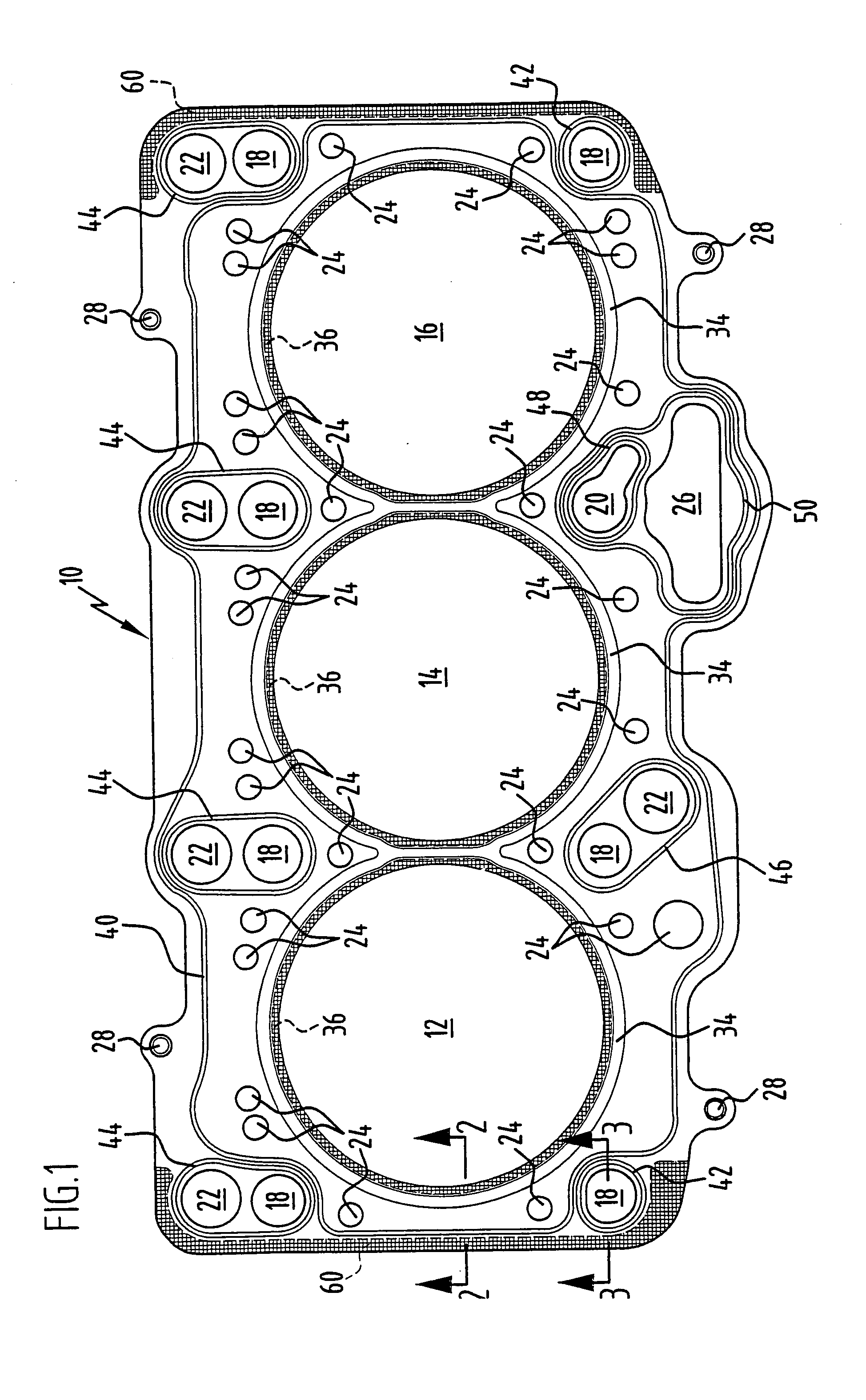
[0017] As is apparent from the preceding explanations, component warpages or deformations occur in the case of multi-cylinder engines, in particular, in the area of the longitudinal ends of the engine. In the case of a cylinder head gasket with an elongated gasket plate which has several combustion chamber apertures between its two longitudinal ends, at least two inventive supporting areas, which are arranged in the vicinity of the longitudinal ends of the gasket plate, will, therefore, be expediently provided. In the case of a cylinder head gasket with an elongated gasket plate which has several combustion chamber apertures between its two longitudinal ends, screw apertures for the passage of cylinder head screws are normally provided in the vicinity of these longitudinal ends; when a cylinder head gasket is installed, increased pressing forces result around the cylinder head screws and this applies, in the case of a cylinder head gasket for a multi-cylinder engine, to an even greater extent for the cylinder head screws adjacent to the longitudinal ends of the gasket since these screws are associated only with the two terminal combustion chambers whereas cylinder head screws arranged between adjacent combustion chambers are associated with two respective combustion chambers, for which reason, in preferred embodiments of inventive cylinder head gaskets for multi-cylinder engines, at least two inventive supporting areas are provided which are located in the vicinity of the screw apertures adjacent to the longitudinal ends of the gasket plate.

Problems solved by technology

If a supporting device is formed by beads extending parallel to one another and having a course which is, in the plan view, in a straight line or arc-shaped, the cylinder head gasket clamped between engine block and cylinder head cannot offer any really great resistance to the flattening of the beads since displacement movements of areas of the sheet-metal layer in the plane of the layer transverse to the course of the beads, which occur with the flattening of those beads forming the supporting device, cannot be completely prevented.

Method used


Image

  • Cylinder head gasket
  • Cylinder head gasket
  • Cylinder head gasket

Examples


Embodiment Construction

[0028] The three-layered (cf. FIGS. 2 to 4) cylinder head gasket illustrated in a plan view in FIG. 1 has a gasket plate 10 with a plurality of apertures, namely three combustion chamber apertures 12, 14 and 16, seven screw holes 18 of a, as usual, circular shape, an aperture 20 for the passage not only of a cylinder head screw but also of lubricating oil, five additional, circular apertures 22 for the passage of lubricating oil, several cooling water apertures 24 of different sizes as well as an oil return aperture 26 for the return flow of lubricating oil from the cylinder head to the engine block. Compression rivets, with which the three sheet-metal layers of the cylinder head gasket are connected to one another, are designated as 28.

[0029] As is apparent from FIG. 1 in conjunction with FIGS. 2 to 4, the gasket plate 10 is composed of two cover sheet-metal layers 30 and a carrier sheet-metal layer 32 arranged therebetween. The cover sheet-metal layers consist of a metal sheet of...


PUM


Abstract

Cylinder head gasket with a gasket plate formed by at least one layer of sheet metal and at least one combustion chamber aperture which is enclosed by a sealing device serving the purpose of sealing the combustion chamber, wherein in order to reduce any warpages of an engine block and/or of a cylinder head a supporting device is provided radially outside the sealing device on the gasket plate; so that the supporting device can be produced in a material-saving and procedurally reliable manner, the supporting device has an area of the sheet-metal layer which is thickened by way of embossing and does not enclose any of the apertures of the gasket to be sealed completely or almost completely and has at least one embossed supporting bead with a meandering shape or a two-dimensional pattern of cup-like recesses and associated elevations.

Description

[0001] The present disclosure relates to the subject matter disclosed in German application No. 10 2004 012 905.3 of Mar. 17, 2004, which is incorporated herein by reference in its entirety and for all purposes. BACKGROUND OF THE INVENTION [0002] The invention relates to cylinder head gaskets, namely essentially metallic cylinder head gaskets which have a gasket plate, the main component of which is a layer of sheet metal or several layers of sheet metal placed on top of one another. In particular, the invention relates to cylinder head gaskets for multi-cylinder engines; insofar as such engines do not have a separate cylinder head gasket for each individual cylinder, the cylinder head gasket has an elongated gasket plate with several combustion chamber apertures which are arranged in a row one behind the other, the centers of which may, however, also be located on a zigzag line extending in the longitudinal direction of the gasket plate. [0003] The locations of a cylinder head gask...

Claims


Application Information

Patent Timeline
Patent Type & Authority Applications(United States)
IPC IPC(8): F02F11/00F16J15/08
CPCF16J15/0818F16J2015/0868F16J15/0825
Inventor DETMANN, KLAUSOPITZ, STEFANGRUHLER, TOBIASSCHAIBLE, FRANK
Owner ELRINGKLINGER AG
Why Eureka
Try Eureka