Display device

a display device and display technology, applied in static indicating devices, instruments, electroluminescent light sources, etc., can solve the problems of large set size, degradation of contrast, and inability to obtain high luminance, and achieve the effect of promoting high luminance and not degrading contras

Active Publication Date: 2005-09-22
SANYO ELECTRIC CO LTD
View PDF9 Cites 4 Cited by
  • Summary
  • Abstract
  • Description
  • Claims
  • Application Information

AI Technical Summary

Benefits of technology

[0010] It is an object of the present invention to provide a display device capable of promoting ...

Problems solved by technology

In such a conventional display device (first conventional example), there is a problem in that “Vmodmax” cannot be set sufficiently large due to performance of the data driver 11 and thereby high luminance cannot be obtained.
In the se...

Method used


Image

  • Display device
  • Display device
  • Display device

Examples


example 1

[A] EXAMPLE 1

[0045] First, an example in the case of applying this example to a passive display is described.

[1] Description of Concept of the Present Invention

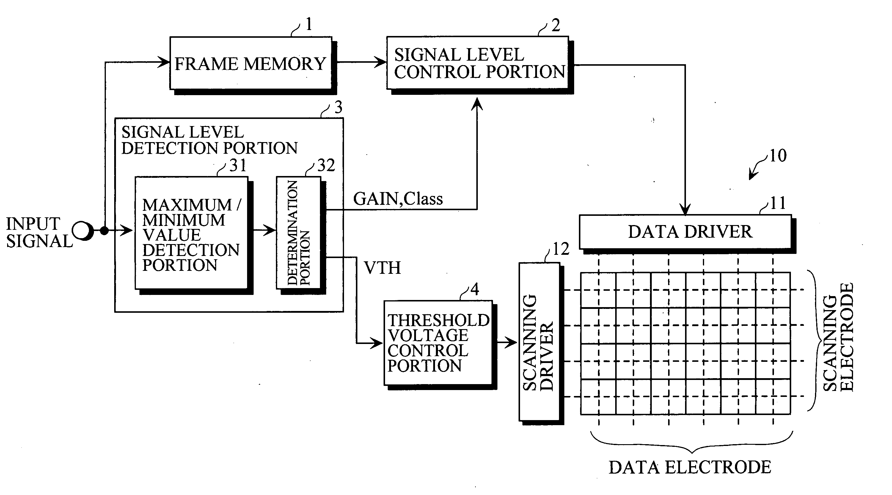
[0046] It is assumed that, when a signal level is expressed by eight bits, the minimum value of the signal level in one screen is 128 and the maximum value thereof is 255.

[0047]FIG. 5 shows an example of the control in the first conventional example shown in FIG. 3. In the first conventional example, the threshold voltage “Vth” is set to the light-emission starting voltage “Vstart”. As shown in FIG. 5, in the frame, the applied voltage to the light-emitting element is “Vb” when the signal level is the minimum value (128) of the frame, whereas the applied voltage to the light-emitting element is “Vth+VmodMAX” when the signal level is the maximum value (255) of the frame. Accordingly, the range of the light-emission luminance is the luminance range of “Lb” to “Le”, which corresponds to the range of the applied voltage of “V...

example 2

[B] EXAMPLE 2

[1] Description of Concept of the Present Invention

[0074] It is assumed that, when a signal level is expressed by eight bits, the minimum value of the signal level in one screen is 0 and the maximum value thereof is 128.

[0075]FIG. 12 shows an example of control in the second conventional example shown in FIG. 4. In the second conventional example, the threshold voltage “Vth” is set to “Va” which is a higher value than the light-emission starting voltage “Vstart”. As shown in FIG. 12, in the frame, the applied voltage to the light-emitting element is “Va” when the signal level is the minimum value (0) of the frame, whereas the applied voltage is “Vb” when the signal level is the maximum value (128) of the frame. Accordingly, the range of the light-emission luminance is the luminance range of “La” to “Lb”, which corresponds to the range of the applied voltage of “La” to “Vb”.

[0076] In the present invention, as shown in FIG. 13, the threshold voltage “Vth” is set to th...

example 3

[C] EXAMPLE 3

[0100] In Examples 1 and 2, although the signal level detection portion 3 updates the signal level detection result (“Class”, “GAIN” and “VTH”) for every one frame (every several frames), the signal level detection portion 3 may be arranged to update the signal level detection result (“Class”, “GAIN” and “VTH”) only when a scene change is detected.

[0101]FIG. 16 shows an electric configuration of a display device. In FIG. 16, the same constituents as those in FIG. 7 are provided with the same reference numerals as in FIG. 7. Hence descriptions of those constituents are omitted in FIG. 16.

[0102] In this display device, a scene change detection portion 5 is provided for detecting whether a scene has changed or not between the present frame and a frame immediately preceding to the present frame, based upon an input signal of the present frame and an input signal of the immediately preceding frame, obtained from the frame memory 1. As the scene change detection portion 5, ...


PUM


Abstract

A display device includes a self light-emitting display in which data electrodes and scanning electrodes are arranged in matrix form, and a modulating voltage is applied to the data electrode side while a threshold voltage is applied to the scanning electrode side, the device including: a signal level range determination means for digitally processing an input signal to determine a signal level range of the input signal for every prescribed frame number unit; a threshold voltage control means for controlling a threshold voltage based upon a determination result by the signal level range determination means; and an input signal correction means for correcting an input signal level based upon a determination result by the signal level range determination means.

Description

BACKGROUND OF THE INVENTION [0001] 1. Field of the Invention [0002] The present invention relates to a display device comprising a self light-emitting display. [0003] 2. Description of the Related Art [0004] As shown in FIG. 1, a self light-emitting display 10 is known in which data electrodes and scanning electrodes are arranged in matrix form, and a modulating voltage is applied by a data driver 11 to the data electrode side while a threshold voltage is applied by an operation driver 12 to the scanning electrode side. The display 10 as thus configured is called a passive display. [0005]FIG. 2 shows a light-emitting characteristic of a self light-emitting element for use in the self light-emitting display. [0006] As shown in FIG. 2, the self light-emitting element starts emitting light upon application of a voltage not lower than a light-emission starting voltage “Vstart”. The light-emitting luminance increases as the voltage applied to the self light-emitting element becomes highe...

Claims


Application Information

Patent Timeline
IPC IPC(8): H01L51/50G09G3/20G09G3/30G09G3/32H05B33/14
CPCG09G3/32G09G2300/0809G09G2360/16G09G2320/066G09G2320/0238
Inventor AMANO, RYUHEI
Owner SANYO ELECTRIC CO LTD
Why Eureka
Try Eureka