Optical system for laser range finder

a laser range finder and optical system technology, applied in the field of laser range finders, can solve the problems of affecting the measuring accuracy of the range finder, reducing the signal-to-noise ratio, increasing the cost and hurting the eye of the operator, and achieving the effect of improving the efficiency of light energy utilization, avoiding interference between the emitted and received light beams, and uniform optical signal carriers

Active Publication Date: 2005-09-22
ASIA OPTICAL INT LTD
View PDF5 Cites 13 Cited by
  • Summary
  • Abstract
  • Description
  • Claims
  • Application Information

AI Technical Summary

Benefits of technology

[0013] By the provision of the optical system of the present invention, the efficiency of light energy utilization is increased, the interference between the emitted and received light beams is avoided, and the requirement of equal optical path length about the received reflected light beam is met, so that the uniformity of the optical signal carrier is also achieved. By the light refraction effect of a prism, light reflected from both short distances and long distances can be received. The signal to noise ratio of the received signal is increased, so that the measuring precision and accuracy of the range finder may be increased. The stability and reliability of the system are also increased as a result of a relatively simple design of the present system. In comparison with the prior art, the optical system for a ranger finder in accordance with the present invention has the following advantages:
[0014] 1. By using a polygonal prism to compensate for the phase difference and to change the light path, both short distance measurement and long distance measurement can be performed, and the signal to noise ratio is increased.
[0015] 2. By using a polygonal prism to sufficiently refract the reflected light, the light energy uniformity within the entire measuring range of the range finder can be achieved, and the light energy can be sufficiently used.
[0016] 3. No excessive additional configurations or elements are required by the present invention, whereby the production cost is reduced.
[0017] 4. The present optical system is a simple design with a reduced number of elements and with no moving elements, thereby facilitating mass production and increasing the reliability and durability of operation.
[0018] 5. The efficiency of light energy utilization has been considered by the present invention, so that flexibility exists in selecting specific laser emitters and APDs, and thus the production cost can be reduced.

Problems solved by technology

Additionally, the light has the diffusibility characteristic, and thus the target object can only reflect a portion of the transmitted light for reception by the laser receiver.
Furthermore, the ambient rays and dust particles etc. may interfere with or influence the reflected light, causing reduction of the signal to noise ratio, thereby affecting the measuring precision of the range finder.
One solution to this problem is to increase the laser transmitting power, which results in increased cost and hurt to the operator's eye.
Distance measurement by laser encounters many technical difficulties in short distance and high precision applications.
These technical difficulties include the reception of the reflected light from a target object at a short distance, the acceptable light amount limit of the APD, the requirement of equal optical path length for high precision distance measurement, and so on.
However, this proposal may cause bending and scattering of light to some extent.
One problem with this proposal is that the prism 31 may also refract the reflected light from some distant target objects, which results in insufficient light energy for the light guide.
One disadvantage for this solution is that the configuration of the diffractive element 41 is relatively complex, and thus is not cost-effective.
Although the above-mentioned conventional solutions are applicable to some actual applications, no consideration can be found in the above references concerning the efficiency ratio of the reflected light to the emitted light and the requirement of equal optical path length as well, whereby the signal accuracy thus cannot be increased.
Secondly, some solutions require motor driving, or require insertion / removal of a specific element into / from the optical system when measuring different distances to near or distant target objects.
These additional configurations or elements bring instability to the system, thereby decreasing the reliability of the system and also increasing the manufacturing cost of the system.

Method used


Image

  • Optical system for laser range finder
  • Optical system for laser range finder
  • Optical system for laser range finder

Examples


Embodiment Construction

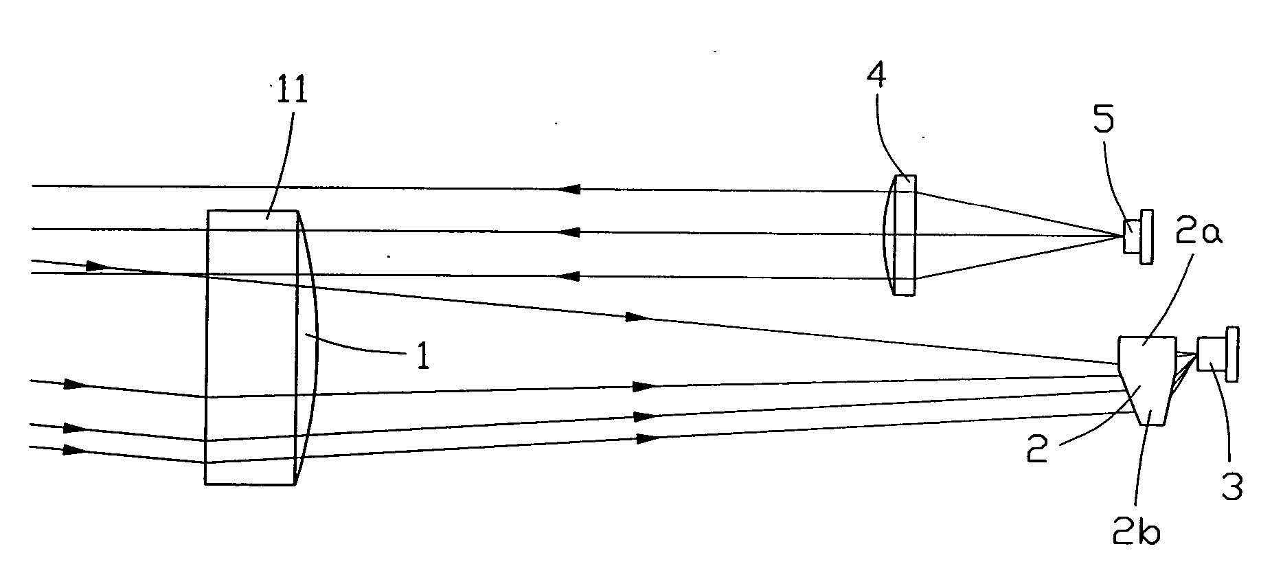
[0028] Referring to FIG. 5, an optical system for a laser ranger finder in accordance with the present invention consists of a light receiving aspheric lens 1, a polygonal prism 2, an optical receiver 3 (preferably an APD), a collimating lens 4 and a laser emitter 5 (preferably a laser diode (LD)). The laser emitter 5 functions as a light source to generate and emit laser light pulses. The emitted laser light beam is emitted through a collimating lens 4 arranged in front of the laser emitter 5 in the direction of the optical axis of the collimating lens 4 as a parallel light beam. The parallel light beam is directed to a target object (not shown) to be measured. When applicable, the target object may be positioned on an auxiliary cooperative target, such as a surveyor's pole, at the same distance. The auxiliary cooperative target helps to reflect the laser light beam more effectively, which allows the optical receiver 3 to generate an electric signal with increased ratio of signal t...


PUM


Abstract

An optical system for a laser range finder comprises a laser emitter (5), a collimating lens (4) positioned in front of the laser emitter an optical receiver (3), a light receiving aspheric lens (1) for converging reflected light from a target object to be measured on the optical receiver, and a polygonal prism (2) disposed between the light receiving aspheric lens and the optical receiver. The light receiving aspheric lens defines a cutout in a position corresponding to a laser light beam emitted by the laser emitter for allowing passage of the laser light beam therethrough. The polygonal prism consists of a first portion and a second portion refracting the reflected light at different refraction angles for light path compensating purposes.

Description

BACKGROUND OF THE INVENTION [0001] 1. Field of the Invention [0002] The present invention relates to a laser range finder, and particularly relates to an optical system for a laser range finder. [0003] 2. Description of Prior Art [0004] A laser range finder is one of the main devices for distance measurement. A common type of laser range finder usually applies a laser emitter as a light source for transmitting a modulated laser light beam to a target object to be measured. The target object reflects and returns the laser light beam to a laser receiver, which is commonly an avalanche photo diode (APD) to convert the optical signal into an electric signal. The distance to the target object is determined by multiplying the light velocity by the time interval between the pulse emission time and the reflected beam reception time. [0005] However, as the light velocity is an extremely large value, the processing of electric signals must be very careful and accurate to obtain an accurate ti...

Claims


Application Information

Patent Timeline
Patent Type & Authority Applications(United States)
IPC IPC(8): G01C3/08G01S7/481G03B17/00
CPCG01S7/4811
Inventor HUA-TANG, LIUHUI-QING, CHENHAI HUA, CHEN
Owner ASIA OPTICAL INT LTD
Why Eureka
Try Eureka