Driving method of optical modulator, and optical transmitter and optical transmission system using same

a technology of optical modulator and driving method, which is applied in the direction of electromagnetic receiver, electromagnetic transmission, transmission, etc., can solve the problems of conventional transmission technique, high cost of dispersion compensation fiber, and inability to achieve ultrahigh-speed optical transmission without dispersion compensation, etc., and achieve the effect of suppressing transmission waveform deterioration

Inactive Publication Date: 2005-09-22
FUJITSU LTD
View PDF5 Cites 7 Cited by
  • Summary
  • Abstract
  • Description
  • Claims
  • Application Information

AI Technical Summary

Benefits of technology

[0009] The present invention has been accomplished in view of the above problems, and it is an object of the present invention to realize a driving method of an optical modulator, which enables long-distance transmi...

Problems solved by technology

However, since the dispersion compensation fiber is expensive, a technique for transmitting ultrahigh-speed optical signals without dispersion compensation is required.
However, the conventional technique has problems as described below.
However, realization of an electric circuit capable of performing such a high-speed operation is not easy, and in the current technology, a large-scale control circuit such as a CPU is required, thereby causing a problem in that small size and low cost cannot be easily achieved.
Moreover, since the frequency characteristic of the equali...

Method used


Image

  • Driving method of optical modulator, and optical transmitter and optical transmission system using same
  • Driving method of optical modulator, and optical transmitter and optical transmission system using same
  • Driving method of optical modulator, and optical transmitter and optical transmission system using same

Examples


first embodiment

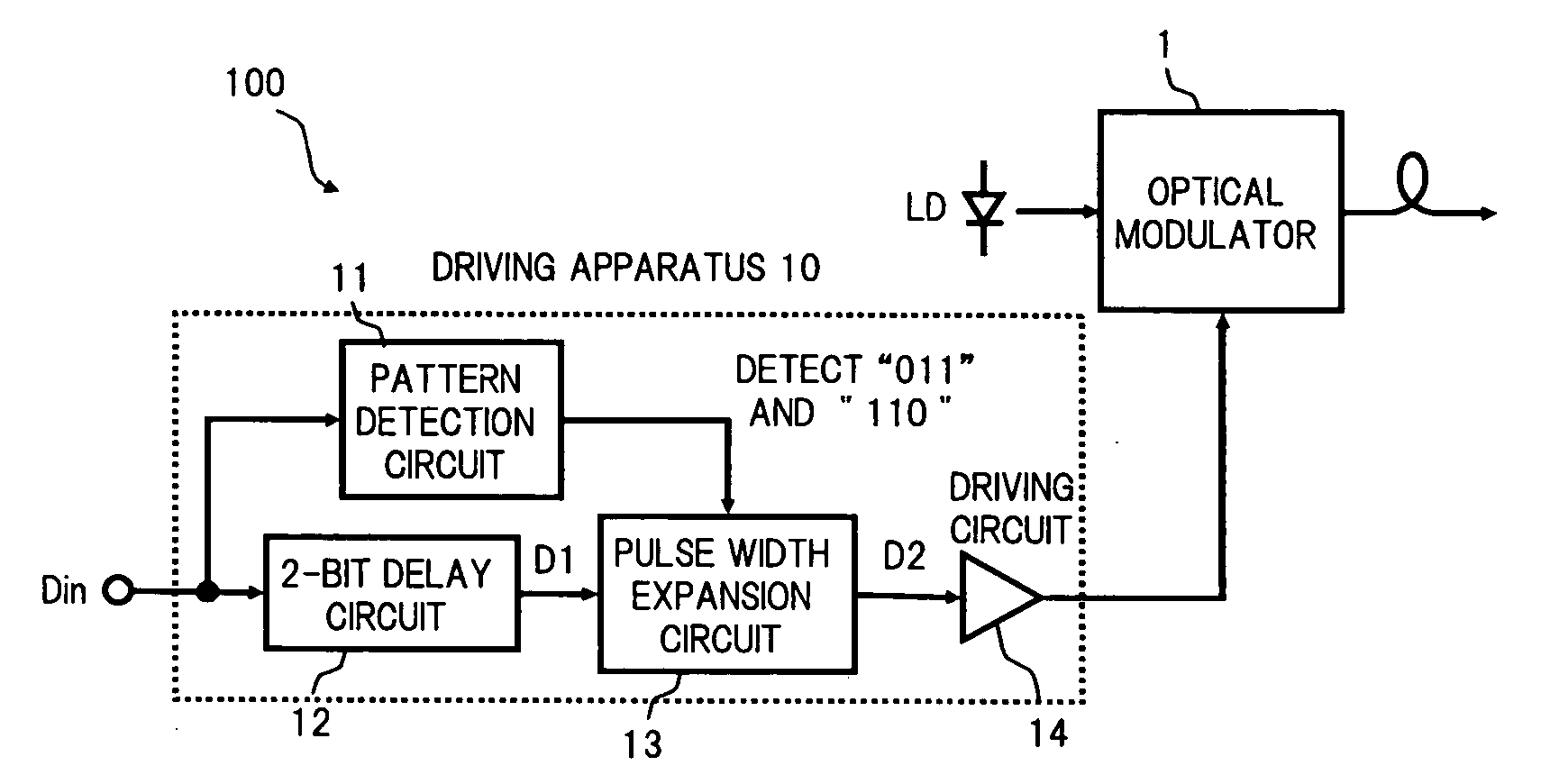
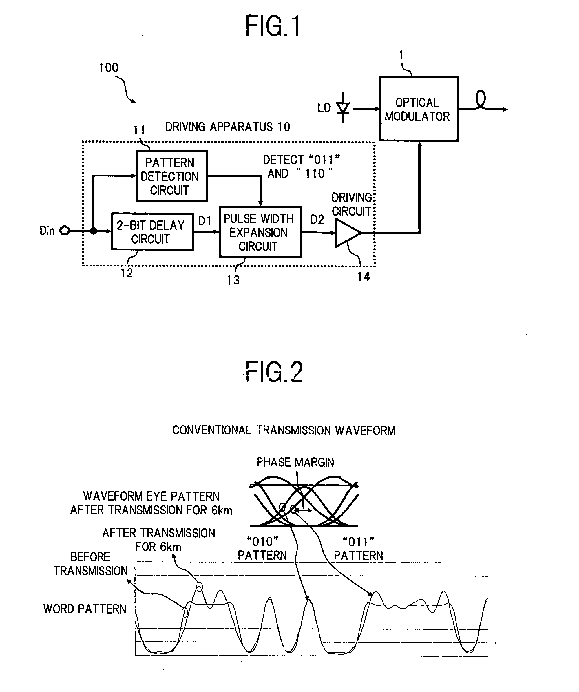
[0052]FIG. 1 is a diagram showing a configuration of an optical transmitter using a driving method for an optical modulator according to the present invention.

[0053] In FIG. 1, an optical transmitter 100 in the present embodiment comprises, for example, an optical modulator 1 which generates an optical signal modulated in accordance with an externally given data signal Din to send out this optical signal to a transmission path, and a driving apparatus 10 for driving the optical modulator 1.

[0054] The optical modulator 1 is a known optical device in which a Mach-Zehnder type waveguide and a signal electrode are formed, for example, on a Z-cut LN substrate, as in the conventional configuration as shown in FIG. 24, and a driving signal from the driving apparatus 10 is applied to the signal electrode, so that an emitted light to be provided to the Mach-Zehnder waveguide from a light source (LD) is modulated and then output. Here, one example of the Mach-Zehnder type optical modulator u...

second embodiment

[0080] Next, there will be described the optical transmitter according to the present invention.

[0081]FIG. 12 is a diagram showing a configuration of the optical transmitter according to the second embodiment.

[0082] As shown in FIG. 12, the optical transmitter 100 in this embodiment is provided with a pattern detection circuit 11′ which detects the “010” pattern, instead of the pattern detection circuit 11 which detects the respective patterns of “011” and “110” in the first embodiment (FIG. 1), and also a driving apparatus 10′ provided with a pulse width reduction circuit 13′, instead of the pulse width expansion circuit 13. The respective configurations of the driving apparatus 10′ other than the pattern detection circuit 11′ and the pulse width reduction circuit 13′, and the optical modulator 1 are the same as those in the first embodiment, and hence the description thereof is omitted.

[0083] Specifically, the pattern detection circuit 11′ is configured using a 3-bit shift regis...

third embodiment

[0086] Next, there will be described the optical transmitter according to the present invention.

[0087]FIG. 15 is a diagram showing a configuration of the optical transmitter according to the third embodiment.

[0088] In FIG. 15, the point where the configuration of this optical transmitter 100 is different to that of the second embodiment shown in FIG. 12, is that in the driving apparatus 10′ there is provided a pulse width expansion circuit 16 between the 2-bit delay circuit 12 and the pulse width reduction circuit 13′. The configuration other than this is the same as for the case of the second embodiment.

[0089] To the pulse width expansion circuit 16 is applied the data signal D1 output from the 2-bit delay circuit 12, and a data signal D1′ is generated for which the pulse width of all of the “1” signals in the data signal D1 is expanded by a previously set length, and this data signal D1′ is output to the pulse width reduction circuit 13′.

[0090] In the driving apparatus 10′ havi...


PUM


Abstract

An object of the invention is to provide a driving method of an optical modulator, which enables long-distance transmission by effectively suppressing transmission waveform deterioration due to a wavelength dispersion characteristic of a transmission path, and an optical transmitter and an optical transmission system using the driving method. To this end, an optical transmitter to which the driving method of the present invention is applied, includes an optical modulator which generates an optical signal modulated in accordance with a data signal to send out the optical signal to the transmission path, and a driving apparatus therefor, and the driving apparatus comprises: a pattern detection circuit which detects a “011” and a “110” in the data signal; a 2-bit delay circuit which delays the data signal by 2 bits; a pulse width expansion circuit which expands each pulse width in a second bit in the “011” and in a second bit in the “110” in the data signal output from the 2-bit delay circuit, according to the pattern detection result of the pattern detection circuit; and a driving circuit which drives the optical modulator, in accordance with the data signal in which the pulse width is expanded.

Description

BACKGROUND OF THE INVENTION [0001] 1. Field of the Invention [0002] The present invention relates to a driving technique for an optical modulator used mainly for optical communication, and more particularly, relates to a driving method of an optical modulator, which enables long-distance transmission by suppressing transmission waveform deterioration due to a wavelength dispersion characteristic of a transmission path, and an optical transmitter and an optical transmission system using the driving method. [0003] 2. Description of the Related Art [0004] In ultrahigh-speed and long-distance optical communications, waveform collapse of an optical signal becomes large due to a wavelength dispersion characteristic of an optical fiber. Therefore, a dispersion compensation fiber compensating for wavelength dispersion is necessary, in order to transmit the optical signal over a long distance. However, since the dispersion compensation fiber is expensive, a technique for transmitting ultrahi...

Claims


Application Information

Patent Timeline
IPC IPC(8): H04B10/2507H04B10/07H04B10/2525H04B10/516H04B10/54H04B10/588H04B10/61
CPCH04B10/524H04B10/505
Inventor IKEUCHI, TADASHI
Owner FUJITSU LTD
Why Eureka
Try Eureka