Method of applying a continuous adhesive filament to an elastic strand with discrete bond points and articles manufactured by the method

a continuous adhesive and elastic strand technology, applied in the field of elastic strand securement, can solve the problems of reducing the elastic properties of the strand(s), unsatisfactory cost increase, and too much adhesive, and achieves high production speed, high bond strength, and superior process control.

Inactive Publication Date: 2005-09-22
NORDSON CORP
View PDF17 Cites 6 Cited by
  • Summary
  • Abstract
  • Description
  • Claims
  • Application Information

AI Technical Summary

Benefits of technology

[0014] The method may be performed using various types of adhesive filament dispensers and filaments of various cross-sectional shapes and widths. As mentioned above, an expanded swirl or other type of cross-over pattern may be used. In general, however, either overlapping patterns such as swirl patterns, or non-overlapping patterns such as vacillating patterns, may be used to achieve the advantages of this invention. In addition to the above, in which the continuous adhesive filament is moved back and forth or oscillated generally transverse to the direction of movement of the elastic strand, the continuous adhesive filament may be moved back and forth or oscillated generally parallel to the direction of movement of the elastic strand such that discrete points of overlap are formed at spaced apart locations to thereby form the areas of increased adhesive mass. In this case, it may be even more advantageous to use a slot-shaped dispenser for discharging a flatter ribbon shaped filament having a slightly larger width extending transverse to the direction of movement of the elastic strand.
[0015] The present invention generally provides superior process control in elastic strand securing applications. The elastic strands are effectively coated with adhesive masses placed at discrete locations along the strand while retaining high production speeds. The adhesive masses form localized areas characterized by high bond strength between the elastic strand(s) and the substrate. At the same time, the elastic properties of the strand(s) will not be significantly compromised at locations between the adhesive masses and this should provide for better creep resistance or retained elasticity in the final product. Since the adhesive attachment method of this invention provides for increased creep resistance or retained elasticity in the final product, it is possible to use finer denier elastic strands. The invention also enables the use of less adhesive. Each of these aspects of the invention results in reducing the costs associated with manufacturing the product. A further increase in creep resistance should be obtainable if the thinner filament sections between adhesive dots are broken leaving separated, discrete areas of adhesive securing the elastic strand to the flat substrate. Low adhesive add-on rates achieved by the invention also lead to enhanced softness of the manufactured article, and less bleedthrough of adhesive through the substrate(s). This latter advantage allows the use of lower gauge substrates leading to further cost reductions.

Problems solved by technology

In addition to undesirable cost increase, using too much adhesive tends to stiffen the substrate and reduce the elastic properties of the strand(s).
This latter effect leads to reduced elasticity in critical areas of the diaper, such as the waistband, leg cuffs, and standing leg gathers.
In addition, large fiber patterns may obstruct the communication of moisture between layers, such as between an inner layer and an absorbent outer layer.

Method used


Image

  • Method of applying a continuous adhesive filament to an elastic strand with discrete bond points and articles manufactured by the method
  • Method of applying a continuous adhesive filament to an elastic strand with discrete bond points and articles manufactured by the method
  • Method of applying a continuous adhesive filament to an elastic strand with discrete bond points and articles manufactured by the method

Examples


Embodiment Construction

[0031] For purposes of this description, words of direction such as “upward”, “vertical”, “horizontal”, “right”, “left” and the like are applied in conjunction with the drawings for purposes of clarity in the present description only. As is well known, liquid dispensing devices may be oriented in substantially any orientation, so these directional words should not be used to imply any particular absolute directions for an apparatus consistent with the invention.

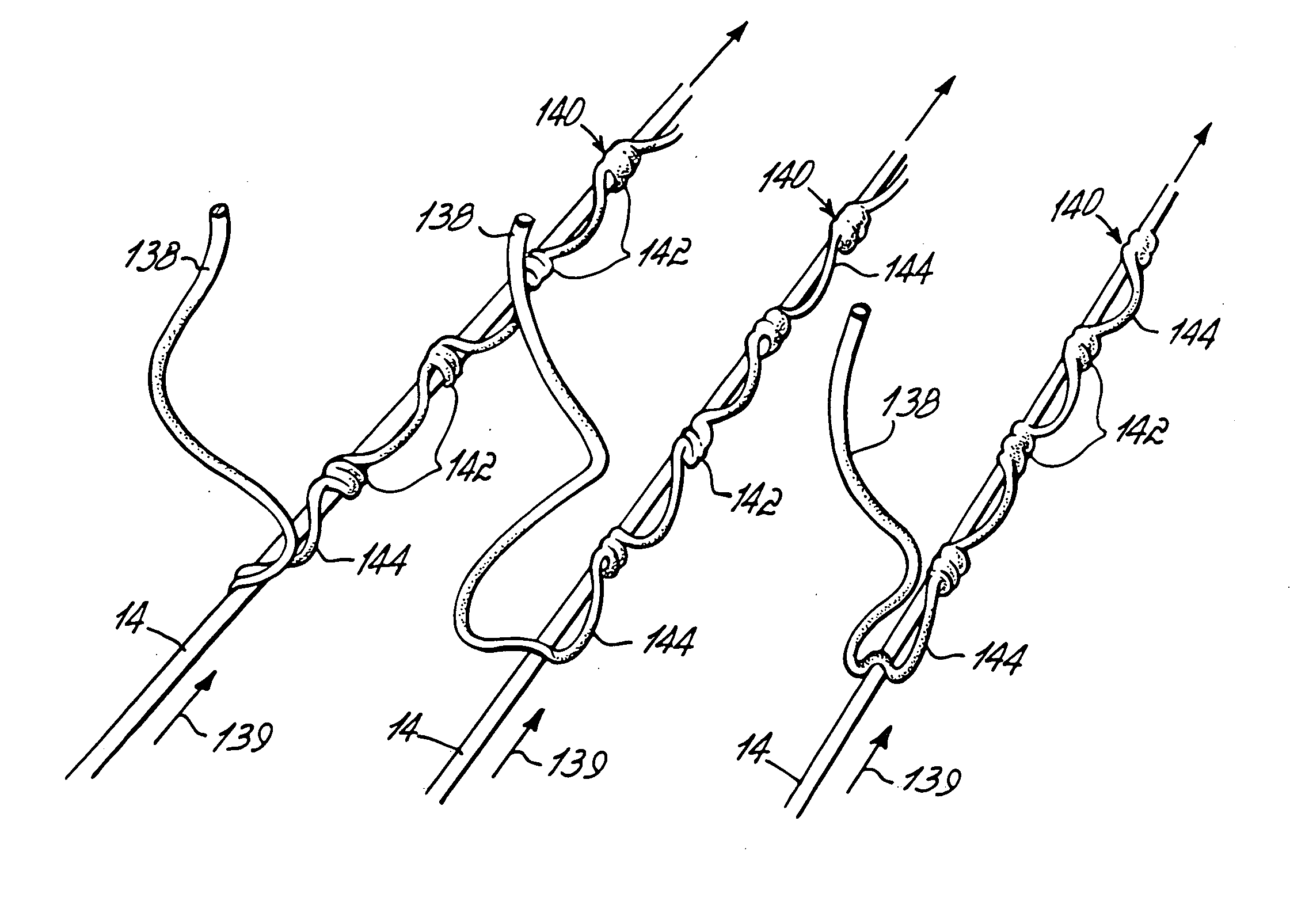
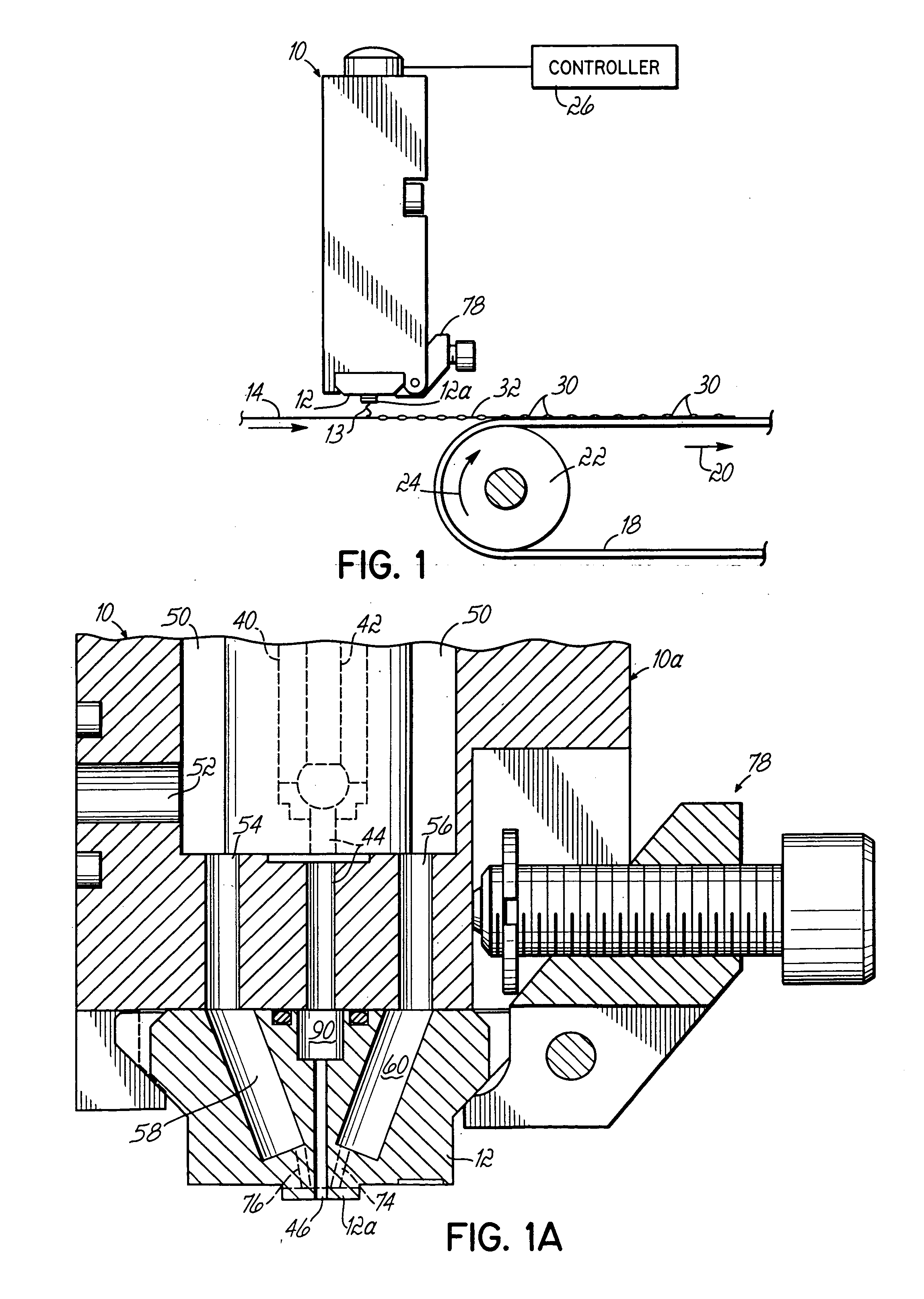
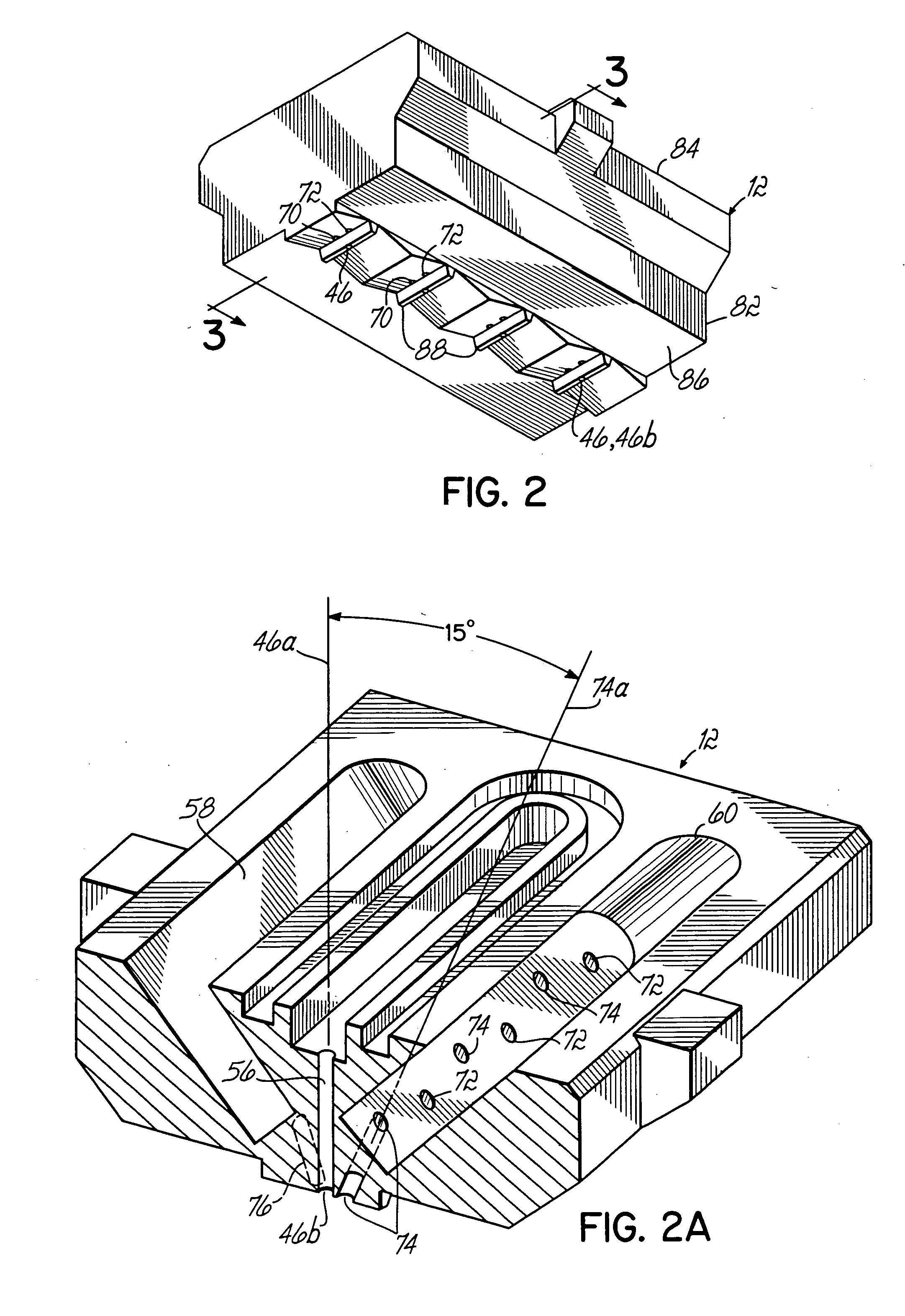
[0032]FIG. 1 illustrates one embodiment of the method of this invention which uses an adhesive dispenser 10 including a nozzle 12. Nozzle 12 may include a circular adhesive discharge orifice, a more elongate slot-shaped orifice, or other types of orifices suitable for dispensing continuous adhesive filaments 13 of a desired width and with a pattern as discussed in greater detail below. In this embodiment, one or more stretched elastic Lycra strands 14 are moving in the direction of arrow 16 and a flat sheet 18 of substrate m...


PUM

PropertyMeasurementUnit
diametersaaaaaaaaaa
diametersaaaaaaaaaa
diameteraaaaaaaaaa

Abstract

A method of securing an elastic strand to a flat substrate or sheet of material moving the elastic strand and the sheet in a converging manner from a first position in which the elastic strand is spaced from the sheet to a second position in which the elastic strand contacts one surface of the sheet. A filament of adhesive is dispensed onto the strand in a pattern configured with adhesive masses coupled by thinner filament sections. The adhesive masses are contacted with the strand when the strand is in the first position. The strand is bonded to the substrate with at least the adhesive masses.

Description

CROSS-REFERENCE TO RELATED APPLICATIONS [0001] This application is a divisional of U.S. application Ser. No. 10 / 282,708, filed Oct. 29, 2002 (pending) and claims the benefit of U.S. Provisional Application No. 60 / 364,613 filed on Mar. 15, 2002 (expired), and the disclosures of which are hereby incorporated by reference herein.FIELD OF THE INVENTION [0002] The present invention generally relates to technology associated with applying continuous adhesive filaments to one or more elastic strands for securing the elastic strands to flat substrates and, more particularly, to the securement of elastic strands to substrates such as those used in producing hygienic articles (e.g., diapers). BACKGROUND OF THE INVENTION [0003] Many reasons exist for dispensing liquid adhesives, such as hot melt adhesives, in the form of a thin continuous filament with a controlled pattern. Conventional patterns used in the past have been overlapping patterns, more specifically a swirling pattern typically cau...

Claims


Application Information

Patent Timeline
Patent Type & Authority Applications(United States)
IPC IPC(8): A61F13/49A61F13/15A61F13/494B05C5/02B05D7/20B05D7/24D06M23/16
CPCY10T428/24802Y10T428/2938B05C5/0275Y10T428/2933B05C5/0241Y10T428/24826Y10T428/249944
Inventor HARRIS, MICHAEL
Owner NORDSON CORP
Why Eureka
Try Eureka