
Reversibly-activated nanostructured battery

a nanostructured battery, reverse activation technology, applied in the field of batteries, can solve the problems of limited in certain aspects and is typically impossible to return the batteries to a reserve sta

Inactive Publication Date: 2005-09-22
ALCATEL-LUCENT USA INC
View PDF11 Cites 19 Cited by
  • Summary
  • Abstract
  • Description
  • Claims
  • Application Information

AI Technical Summary

Benefits of technology

[0006] The present inventors have realized that, while prior reserve and primary batteries were useful in many regards, they were limited in certain aspects. In particular, once the batteries were manufactured and activated (in the case of a reserve battery), it was typically impossible to return the batteries to a reserve state (i.e, to separate the electrolyte from the battery electrodes).
[0007] Therefore, the present inventors have invented a small battery having a nanostructured battery electrode wherein it is possible to reverse the contact of the electrolyte with the battery electrode and, thus, to return a battery to a reserve state after it has been used to generate current. In order to achieve this reversibility, the nanostructures on the battery electrode comprise a plurality of closed cells and the pressure within the enclosed cells is varied. In a first embodiment, the pressure is varied by varying the temperature of a fluid within the cells by, for example, applying a voltage to electrodes disposed within said cells. In a second illustrative embodiment, once the battery has been fully discharged, the battery is recharged and then the electrolyte fluid is expelled from the cells in a way such that it is no longer in contact with the battery electrode.

Problems solved by technology

The present inventors have realized that, while prior reserve and primary batteries were useful in many regards, they were limited in certain aspects.
In particular, once the batteries were manufactured and activated (in the case of a reserve battery), it was typically impossible to return the batteries to a reserve state (i.e, to separate the electrolyte from the battery electrodes).

Method used


Image

  • Reversibly-activated nanostructured battery
  • Reversibly-activated nanostructured battery
  • Reversibly-activated nanostructured battery

Examples


Embodiment Construction

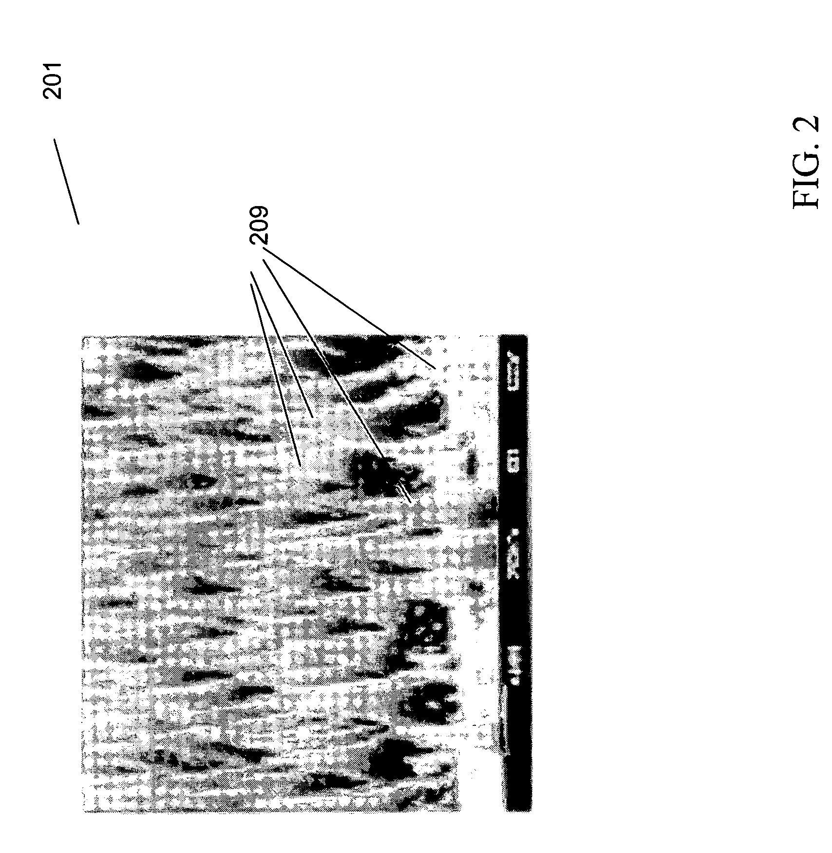
[0020]FIG. 2 shows an illustrative nanopost pattern 201 with each nanopost 209 having a diameter of less than 1 micrometer. While FIG. 2 shows nanoposts 209 formed in a somewhat conical shape, other shapes and sizes are also achievable. In fact, cylindrical nanopost arrays have been produced with each nanopost having a diameter of less than 10 nm. Specifically, FIGS. 3A-3E show different illustrative arrangements of nanoposts produced using various methods and further show that such various diameter nanoposts can be fashioned with different degrees of regularity. Moreover, these figures show that it is possible to produce nanoposts having various diameters separated by various distances. An illustrative method of producing nanoposts, found in U.S. Pat. No. 6,185,961, titled “Nanopost arrays and process for making same,” issued Feb. 13, 2001 to Tonucci, et al, is hereby incorporated by reference herein in its entirety. Nanoposts have been manufactured by various methods, such as by u...


PUM

PropertyMeasurementUnit
diameteraaaaaaaaaa
diameteraaaaaaaaaa
diameteraaaaaaaaaa

Abstract

A battery having a nanostructured battery electrode is disclosed wherein it is possible to reverse the contact of the electrolyte with the battery electrode and, thus, to return a battery to a reserve state after it has been used to generate current. In order to achieve this reversibility, the nanostructures on the battery electrode comprise a plurality of closed cells and the pressure within the enclosed cells is varied. In a first embodiment, the pressure is varied by varying the temperature of a fluid within the cells by, for example, applying a voltage to electrodes disposed within said cells. In a second illustrative embodiment, once the battery has been fully discharged, the battery is recharged and then the electrolyte fluid is expelled from the cells in a way such that it is no longer in contact with the battery electrode.

Description

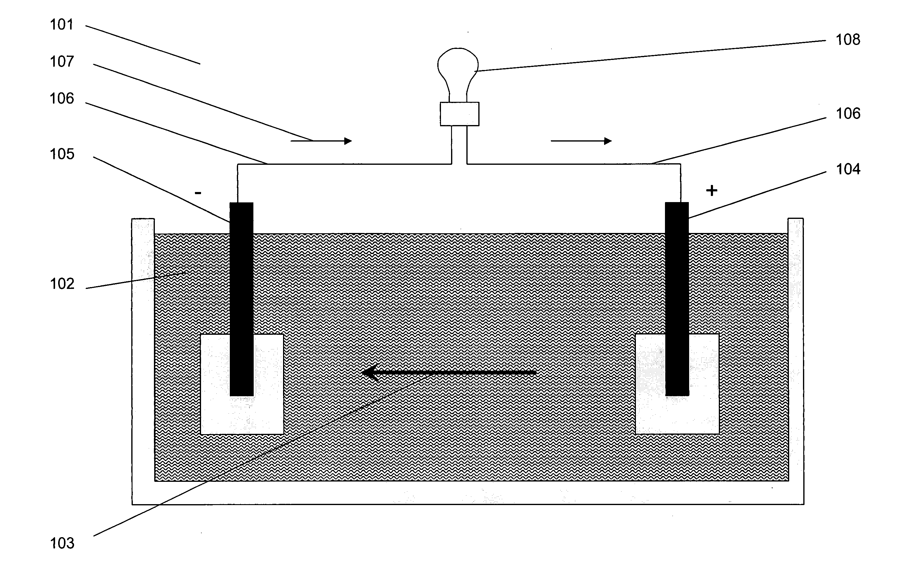
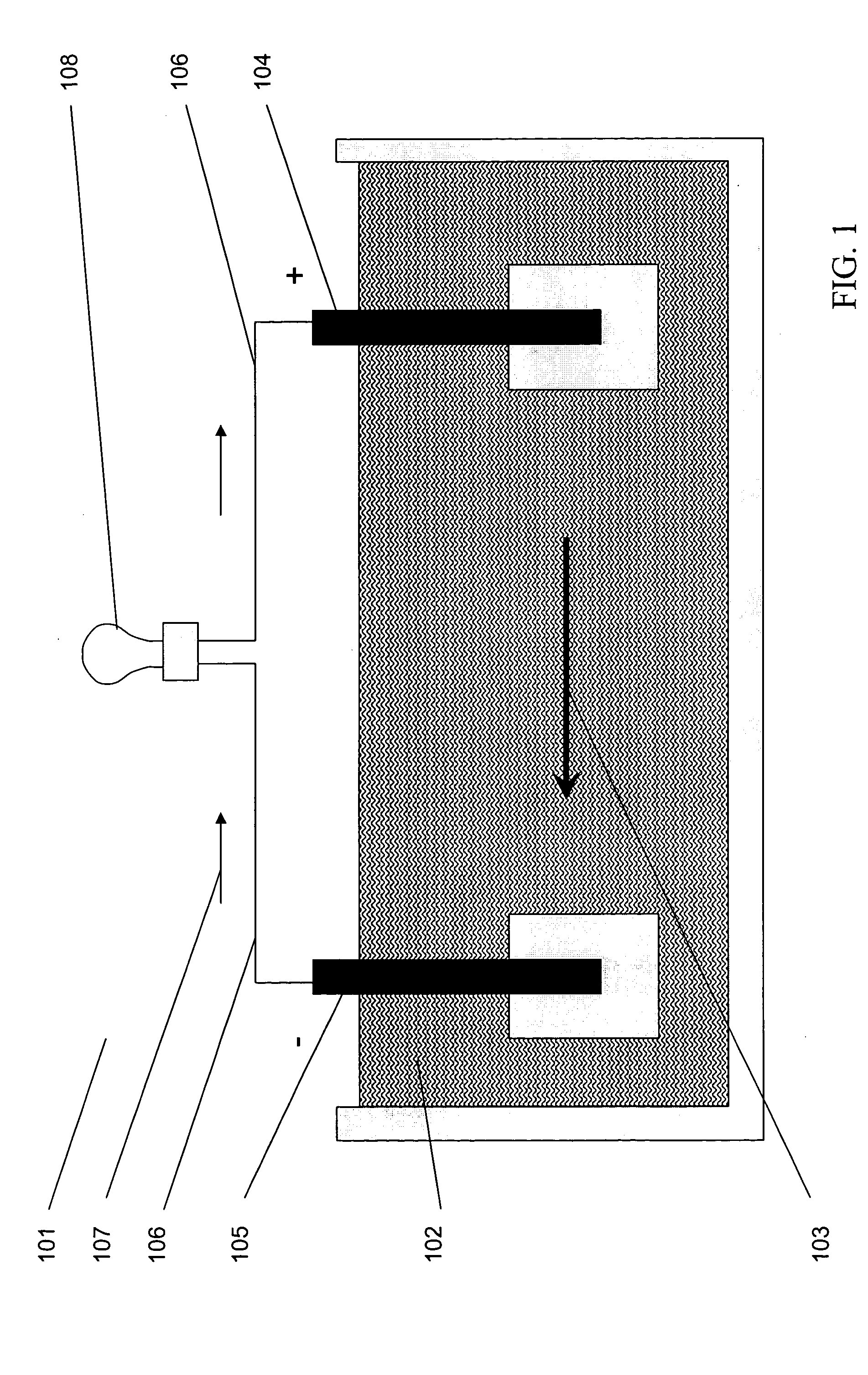
CROSS REFERENCE TO RELATED APPLICATIONS [0001] This application claims subject matter that is described in co-pending United States Patent Application filed simultaneously herewith and entitled “Nanostructured Battery Having End-Of-Life Cells,” Ser. No. ______ and United States Patent Application filed simultaneously herewith and entitled “Reserve Cell-Array Nanostructured Battery,” Ser. No. ______.FIELD OF THE INVENTION [0002] The present invention relates generally to batteries and, more particularly, to batteries having nanostructured surfaces. BACKGROUND OF THE INVENTION [0003] Many beneficial devices or structures in myriad applications rely on batteries as a power source. A typical liquid-cell battery, such as battery 101 in FIG. 1, is characterized by an electrolyte liquid 102 which provides a mechanism for an electrical charge to flow in direction 103 between a positive electrode 104 and a negative electrode 105. When such a battery 101 is inserted into an electrical circuit...

Claims


Application Information

Patent Timeline
Patent Type & Authority Applications(United States)
IPC IPC(8): H01M4/02H01M4/06H01M6/32H01M6/36H01M6/50H01M10/50
CPCB82Y30/00H01M4/02H01M4/06Y10S977/948H01M6/5038H01M6/5077H01M2004/021H01M6/36
Inventor HODES, MARC SCOTTKOLODNER, PAUL ROBERTKROUPENKINE, TIMOFEI NIKITALYONS, ALAN MICHAELMANDICH, MARY LOUISETAYLOR, JOSEPH ASHLEYWEISS, DONALD
Owner ALCATEL-LUCENT USA INC
Learn More