
Electromagnetic wave shielding structure

a shielding structure and electromagnetic wave technology, applied in the direction of aperture leaage reduction, connection contact material, coupling device connection, etc., can solve the problem of radio in an environment subject to noise, the influence of electromagnetic waves emitted from the outside is liable to be exerted, and the radio is subject to potential differences between the earths of the radio and the antenna booster

Inactive Publication Date: 2005-09-22
OHTSUKA
View PDF16 Cites 20 Cited by
  • Summary
  • Abstract
  • Description
  • Claims
  • Application Information

AI Technical Summary

Benefits of technology

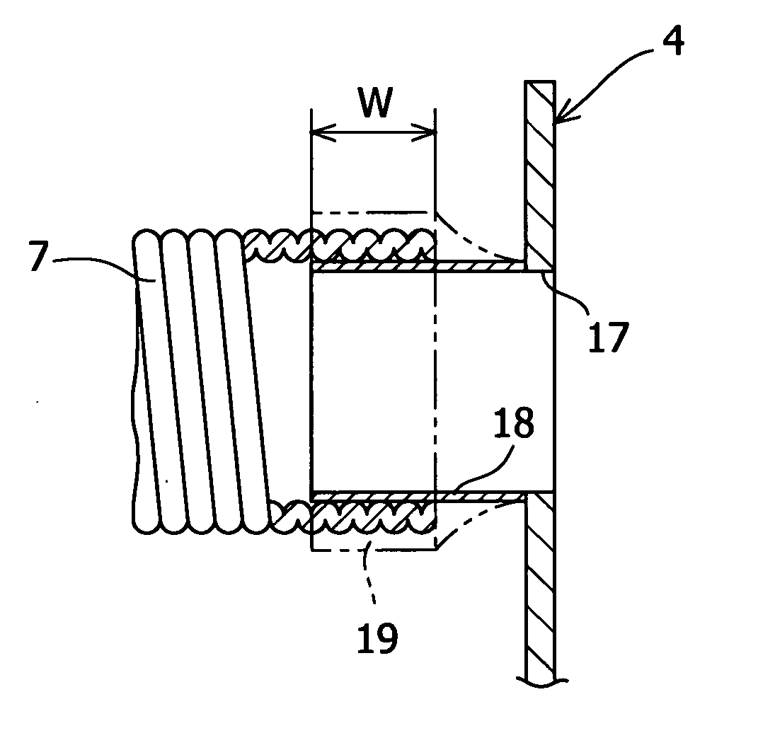
[0013] According to Patent Document 3, as shown in FIG. 19, although the low-voltage harness 71 is covered with a conductive member 72, electromagnetic waves sometimes intrude directly into the body of electrical equipment from the high-voltage harness 73 disposed on the outside of the conductive member 72. In the case where high-frequency waves having a short wavelength intrude into a gap of the back surface of an object or electromagnetic waves are emitted from a harness, great electromagnetic waves are generated in a portion near the electrical equipment of harness. Therefore, the noise treatment in a connecting portion between the harness and the electrical equipment is an important point for alleviating noise.
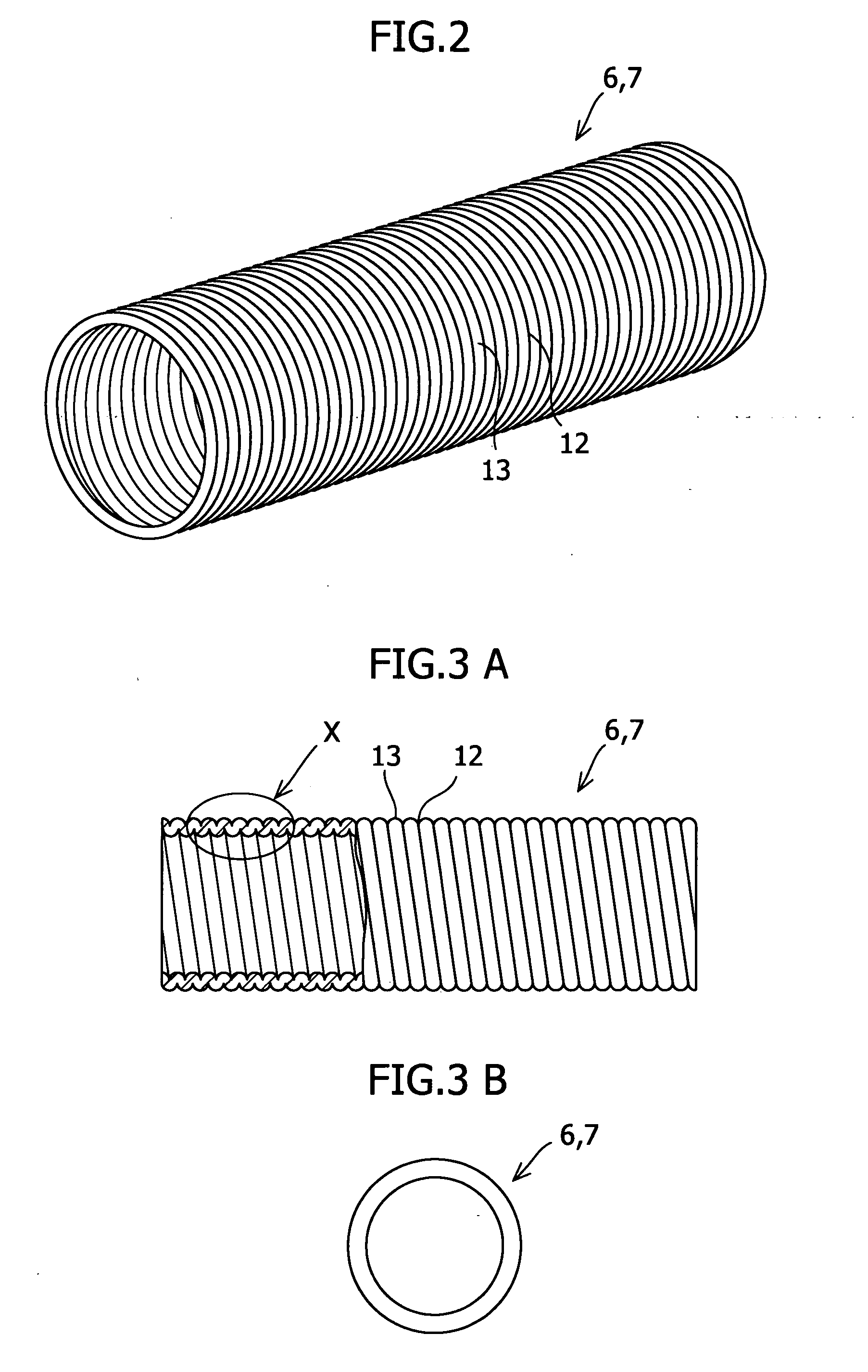
[0019] In the present invention, the cylindrical member can have flexibility, and also the cylindrical member can be made of aluminum.

Problems solved by technology

However, in the case where a distance between the rear glass 51 and a radio mounted on a front instrument panel of vehicle body is long, or in the case where the earthing of the vehicle body is incomplete, a potential difference is produced between the earths of the radio and the antenna booster.
If a slight potential difference exists between the earths, an influence of electromagnetic waves emitted from the outside is liable to be exerted, and the radio is in an environment subject to noise.
Although electromagnetic waves intruding from the aerial wire have been explained, electromagnetic waves sometimes intrude directly into the power source harness or body circuit of audio equipment etc. to create noise.
In this case, it is impossible to effectively protect the electrical equipment generating noise from the electromagnetic waves.

Method used


Image

  • Electromagnetic wave shielding structure
  • Electromagnetic wave shielding structure
  • Electromagnetic wave shielding structure

Examples


Embodiment Construction

[0040] An electromagnetic wave shielding structure in accordance with an embodiment of the present invention will now be described with reference to the accompanying drawings.

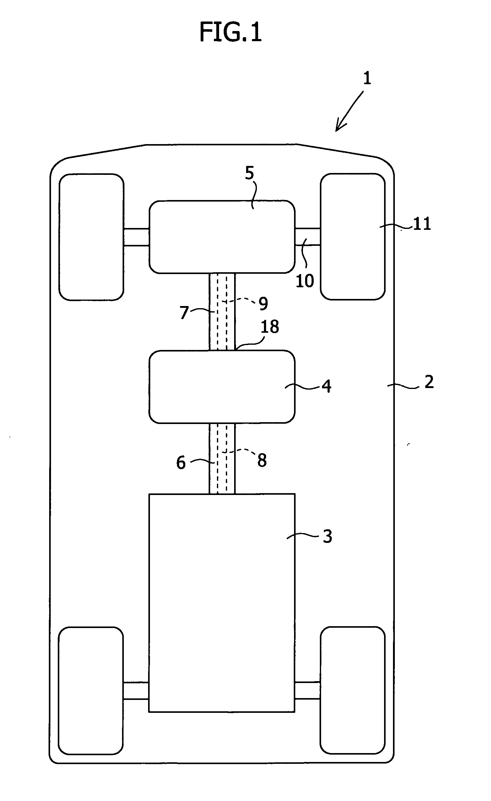
[0041]FIG. 1 is a schematic plan view of an electric vehicle 1. On a vehicle body 2 of the electric vehicle 1, there are arranged a high-voltage direct current power source 3 in which many batteries are disposed, an inverter 4 for converting the direct current into an alternating current, and a driving motor 5 which is driven by the alternating current power source converted by the inverter 4. Between the direct current power source 3 and the inverter 4, a cylindrical member 6 is connected, and between the inverter 4 and the driving motor 5, a cylindrical member 7 is connected. In one cylindrical member 6, a harness 8 for connecting the direct current power source 3 to the inverter 4 is disposed, and in the other cylindrical member 7, a harness 9 for connecting the inverter 4 to the driving motor 5 is disposed...


PUM


Abstract

The present invention provides an electromagnetic wave shielding structure for shielding electromagnetic waves emitted from a harness of electrical equipment. For example, a vehicle body of an electric vehicle is provided with a direct current power source, an inverter, and a driving motor. The direct current power source and the inverter, and the inverter and the driving motor are connected to each other by harnesses, respectively. Around the harnesses, cylindrical members for shielding electromagnetic waves are provided, respectively, so as to cover the harnesses. The peripheral wall of the cylindrical member made of aluminum, on which an uneven portion is formed continuously in the axial direction, shields electromagnetic waves emitted from the harness to the outside.

Description

BACKGROUND OF THE INVENTION AND RELATED ART STATEMENT [0001] 1. Field of the Invention [0002] The present invention relates to an electromagnetic wave shielding structure for shielding electromagnetic waves emitted from a power supply harness or a signal harness of electrical equipment. [0003] 2. Description of Related Art [0004] While automobiles are often mounted with electrical (electronic) equipment, such as audio and video products, many noise generating sources are also present, such as an alternator and a fuel pump. Although an audio product, such as a radio, is usually provided with a circuit for noise suppression, noise is sometimes generated from the audio product due to manufacture error of the automobile or radio interference in a region. Therefore, noise is suppressed by various methods as described below. [0005] For example, according to Japanese Patent Provisional Publication No. 6-291529 (hereinafter referred to as Patent Document 1), as shown in FIG. 16, a radio gla...

Claims


Application Information

Patent Timeline
IPC IPC(8): H01R4/66H01R13/6461H01R13/658H01R13/6581H05K9/00
CPCB60L11/1803H01R2201/26H05K9/0018H02G3/0468B60R16/0222H01R13/6461H01R13/6581Y02T10/7005B60L50/51Y02T10/70
Inventor SHIMODA, AKIO
Owner OHTSUKA
Learn More