Digital, self-calibrating proximity switch

a digital, self-calibration technology, applied in the field of proximity switches, can solve the problems of inability of the sensor, subject to non-purposive triggering, inability to target the sensor, etc., to facilitate communication and/or actuation of devices, facilitate tracking of signal characteristics over time, and compact packaging of a working proximity switch

Active Publication Date: 2005-09-22
BOARD OF TRUSTEES OPERATING MICHIGAN STATE UNIV
View PDF5 Cites 30 Cited by
  • Summary
  • Abstract
  • Description
  • Claims
  • Application Information

AI Technical Summary

Benefits of technology

[0007] The digital switching apparatus according to the present invention affords several advantages over previous, analog switches. For example, the use of a digital controller facilitates tracking of signal characteristics over time, with implementation in software of user-adjustable filtering methods that distinguish purposive activations from non-purposive ones. Also, a self-calibrating mode is enabled by the ability to track signal characteristics over time, such that a slope can be calculated that indicates rate of change. Further, on-board memory and processing capability, combined with a variable state output mechanism, permits the implementation of on-board activation pattern recognition with distinguishable outputs to an external processor. The switching apparatus of the present invention is advantageously useable to facilitate communications and / or actuation of devices by physically challenged people. In comparison to previous, analog proximity switches, this invention allows for a more compact packaging of a working proximity switch. It can be packaged with its own power source and with easily accessed mode controls and status indicators. It can also be incorporated as a modular part of a larger system.

Problems solved by technology

The aforementioned techniques avoid non-purposive triggering of the switching mechanism due to some involuntary movements, such as blinking, but can be subject to non-purposive triggering due to other involuntary movements, such as tremors that can follow a purposive movement.
However, the target area for aiming the sensor is diminished by inability of the sensor to distinguish between mere blinks and purposive closing of the eyelid alone.

Method used


Image

  • Digital, self-calibrating proximity switch
  • Digital, self-calibrating proximity switch
  • Digital, self-calibrating proximity switch

Examples


Embodiment Construction

[0030] The following description of the preferred embodiments is merely exemplary in nature and is in no way intended to limit the invention, its application, or uses.

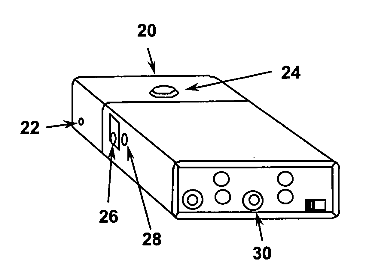
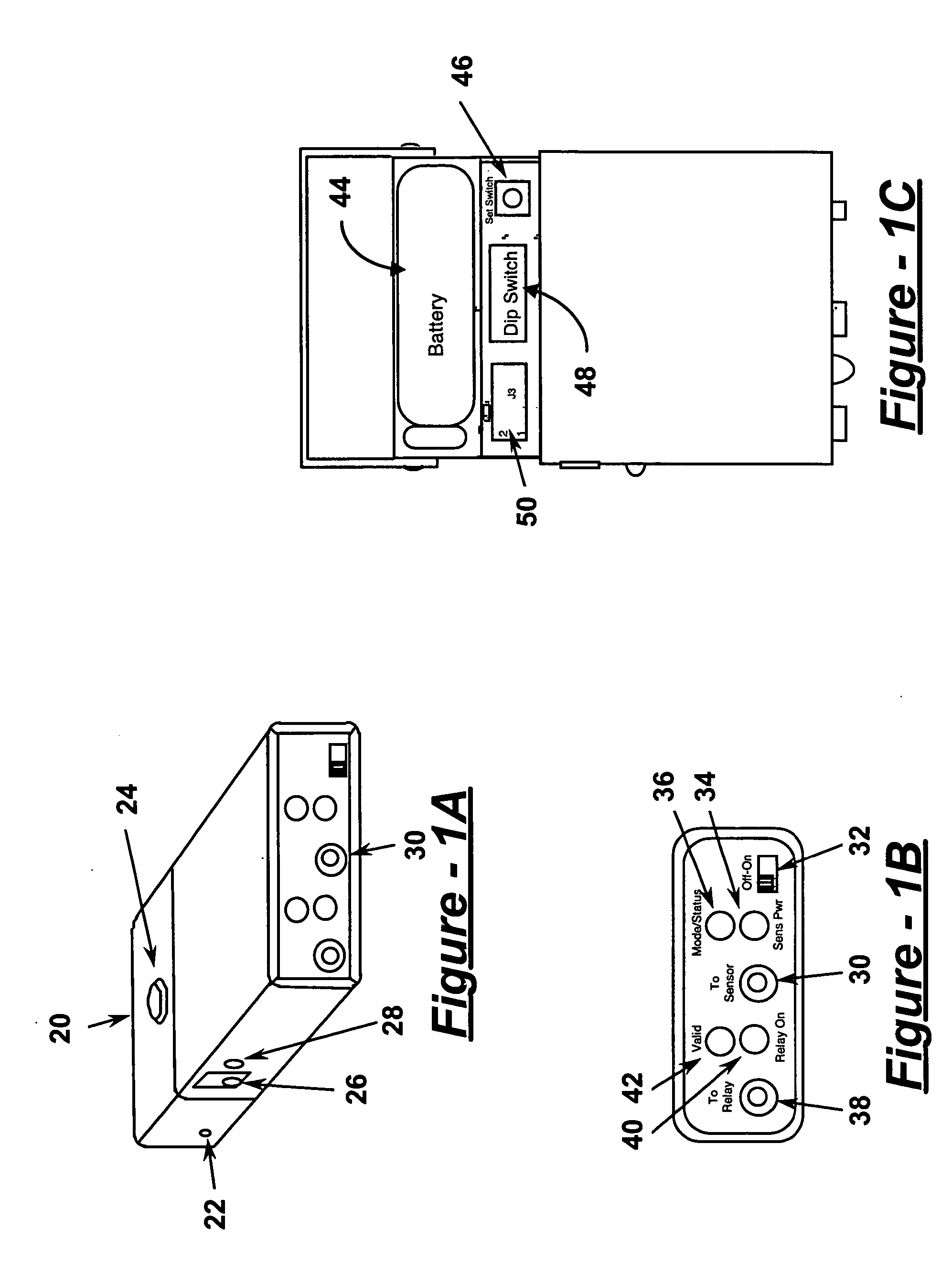
[0031] Referring to FIG. 1A, a preferred embodiment of a digital switching apparatus of the present invention includes a hinged cover 20 having a hinge 22 and a latch release 24. The apparatus also has a charger jack 26, a charge status LED 28, and a sensor jack 30 adapted to connect to several, optional sensor configurations, preferably via a standard tip-ring-sleeve (TRS) connection. Examples of types of sensors that can connect to sensor jack 30 include proximity sensors, EMG sensors, force sensing resistors, visible light and shadow sensors, skin conductivity sensors, capacitive touch sensors, and piezo sensors.

[0032]FIG. 1B illustrates a front panel of the switching apparatus, including sensor jack 30, a power switch 32, a “sensor power” LED 34, and a “mode / status” LED, 36. A relay jack 38 supplies an output sig...


PUM


Abstract

A signal processing system for detecting purposive signals includes an input receiving a signal having a signal characteristic subject to user manipulation. An activation detector compares a property of the signal characteristic to one or more signal characteristic property thresholds over time. A filter module determines whether the signal characteristic is purposively manipulated based on an amount of time preceding or following an occurrence of the property exceeding or falling below one or more signal characteristic property thresholds.

Description

CROSS-REFERENCE TO RELATED APPLICATIONS [0001] This application claims the benefit of U.S. Provisional Application No. 60 / 548,245, filed on Feb. 27, 2004. The disclosure of the above application is incorporated herein by reference in its entirety for any purpose.FIELD OF THE INVENTION [0002] The present invention generally relates to proximity switches, and particularly relates to a signal processing unit capable of distinguishing between purposive and non-purposive signals. BACKGROUND OF THE INVENTION [0003] A typical proximity switch consists of a sensor, a signal-processing unit, and an output port. The signal-processing unit detects the distance of the sensor from the surface of a target object, the “activating surface”. In prior art designs, when this distance is less than a certain magnitude, the “activation distance”, the output port is switched to its “on” state. [0004] Previous proximity switches have had either a fixed activation distance or have required manual calibratio...

Claims


Application Information

Patent Timeline
Patent Type & Authority Applications(United States)
IPC IPC(8): G01S17/04G06F15/00H03K17/94
CPCG01S17/026H03K17/941H03K2217/94021G01S7/497H03K2217/94108H03K2217/94116H03K2217/94026G06F3/013G06F3/017G01S17/04
Inventor BLOSSER, STEPHEN R.EULENBERG, JOHN B.
Owner BOARD OF TRUSTEES OPERATING MICHIGAN STATE UNIV
Why Eureka
Try Eureka