Auger-anchored beach umbrella

a technology of anchoring and umbrellas, applied in umbrellas, walking sticks, clothing, etc., can solve the problems of limiting the size of umbrella canopy that can practically be used, impractical to utilize mechanisms, and each reference suffers from the disadvantage of relying on the physical strength of the person, so as to maximize the shade area and improve the anchoring

Inactive Publication Date: 2005-09-29
DEVENEZIA CECILIA +1
View PDF45 Cites 22 Cited by
  • Summary
  • Abstract
  • Description
  • Claims
  • Application Information

AI Technical Summary

Benefits of technology

[0010] In an alternate embodiment, the auger is detachable from the motor shaft so that it may be replaced if damaged. This feature also enables the use of one or more alternate augers designed for different ground conditions.
[0011] Due to its improved anchori...

Problems solved by technology

The principal problem with beach umbrellas has been finding a means of securely anchoring them in the ground.
Lack of secure anchoring places a limit on the size of the umbrella canopy that can practically be utilized, since larger canopies are heavier and more vulnerable to gusts of wind.
Lack of secure anchoring also makes it impractical to utilize mechanisms for tilting the umbrella canopy in the direction of the sun so as to maximize the shaded area.
However, each of these references...

Method used


Image

  • Auger-anchored beach umbrella
  • Auger-anchored beach umbrella

Examples


Embodiment Construction

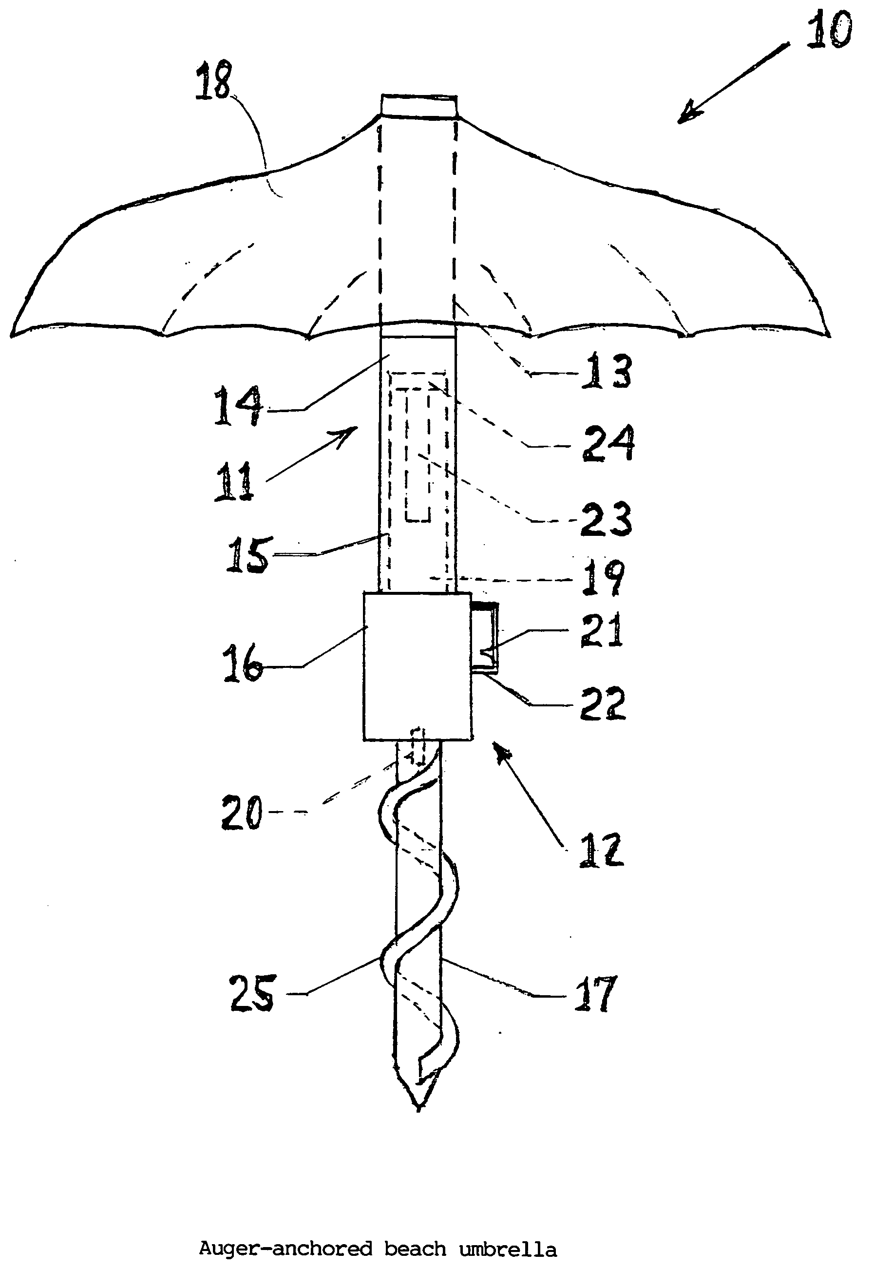
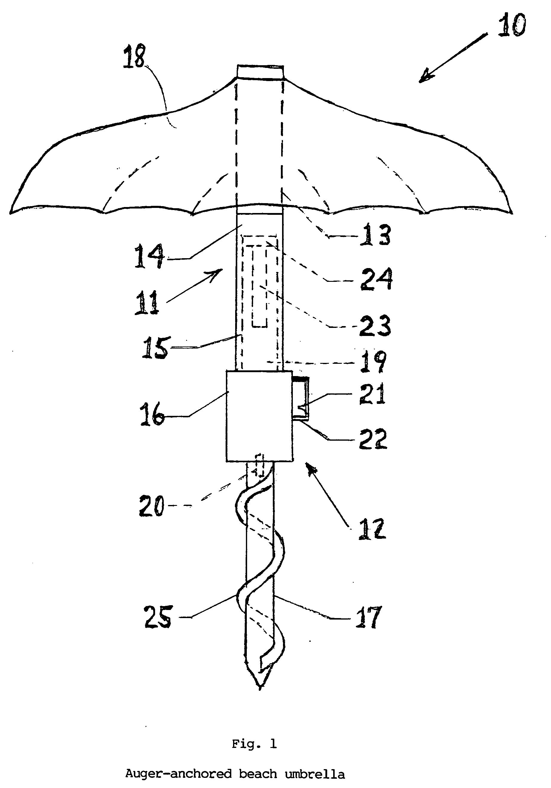
[0013] As shown in FIG. 1, a self-anchoring umbrella embodying the features of the present invention 10 comprises a canopy member 11 and a pole member 12. The canopy member 11 is comprised of an upper tubular element 13 and a lower tubular element 14. The pole member 12 is comprised of an upper element 15, a motor element 16, and an auger 17.

[0014] A spreadable canopy 18 is connected to and supported by the upper tubular element 13 of the canopy member 11. Within the lower tubular element 14 of the canopy member 11 is formed an axial lumen 19. The upper element 15 of the pole member 12 is formed to slide snugly into the axial lumen 19 of lower tubular element 14 of the canopy member 11.

[0015] The motor element 16 of the pole member 12 comprises a reversible electric motor (not shown), having on its lower end an axially-disposed shaft 20, which is coupled to the auger 17. Mounted upon the motor element 16 of the pole member 12 is a switch 21. In the preferred embodiment, the switch...


PUM


Abstract

An auger-anchored beach umbrella has a canopy member for supporting the canopy and a pole member for anchoring the umbrella in the ground. The canopy member has a lower tubular element within which is formed an axial lumen. The pole member has an upper element which slides snugly into the axial lumen of the canopy member. The pole member has a motor element, within which is enclosed a reversible electric motor. Coupled to the motor's shaft is an auger. The motor is electrically connected to one or more batteries and to a switch. The user inserts the pole member into the ground by activating the switch in the forward direction, thereby causing the auger to bore into the ground. In the preferred embodiment, the user grasps a handle attached to the upper element to guide the pole member into the ground and to exert a supplemental downward force on it. After the auger is firmly anchored in the ground, the canopy member is mounted on the pole member by sliding the axial lumen over the upper element of the pole member. When the beach umbrella is removed from the ground, the canopy member is removed from the pole member. The user activates the switch in the reverse direction, thereby causing the auger to disengage from the ground. In the preferred embodiment, the user grasps the handle to guide the pole member out of the ground and to exert a supplemental upward force on it.

Description

BACKGROUND OF THE INVENTION [0001] Beach umbrellas are used to create an area shaded from the sunlight beneath the umbrella canopy. They are particularly useful for bathers at a beach or swimming pool, where there is generally a lack of trees or roofed structures to provide shade. Because a bather's skin is largely exposed, there is a greater need to provide protection from harmful ultraviolet rays, which may cause sunburn or melanomas. The shade and shelter provided by a beach umbrella is also useful in protecting a bather's valuables and shielding perishable items from direct sunlight. [0002] The principal problem with beach umbrellas has been finding a means of securely anchoring them in the ground. Lack of secure anchoring places a limit on the size of the umbrella canopy that can practically be utilized, since larger canopies are heavier and more vulnerable to gusts of wind. Lack of secure anchoring also makes it impractical to utilize mechanisms for tilting the umbrella canopy...

Claims


Application Information

Patent Timeline
IPC IPC(8): A45B3/00A45B5/00A45B11/00E04H12/22
CPCE04H12/2223A45B11/00A45B25/00A45B2023/0012A45B2200/1009
Inventor DEVENEZIA, CECILIADEVENEZIA, PAUL
Owner DEVENEZIA CECILIA
Why Eureka
Try Eureka